GuglioLS
Administrator  Jinma354 LE
Posts: 1,276
|
Post by GuglioLS on Feb 1, 2008 0:05:29 GMT -5
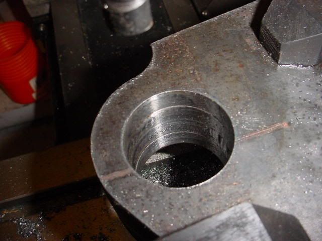
The 1.5" holes in the jaws will be bored out with a ....boring bar  I've never done this before, I consulted Rob he said to "index" on the center - whatever that means, then go as slow as possible, so here goes: 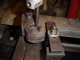 Well not too bad they came out all right and nothing broke, so I guess I done good?  Larry |
|
GuglioLS
Administrator
Jinma354 LE
Posts: 1,276
|
Post by GuglioLS on Feb 1, 2008 0:06:03 GMT -5
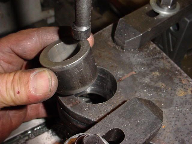
It took several passes, increasing the cut diameter a little at a time for each cut (~.05) till I got close to test fit the DOM:  It fits, I was hoping for a press fit but will have to settle for a slip fit. Not a problem as I have an idea how to clamp them into position for welding.  Larry |
|
GuglioLS
Administrator
Jinma354 LE
Posts: 1,276
|
Post by GuglioLS on Feb 1, 2008 0:06:35 GMT -5
Next was to cut two pieces of 2" x 2" x 1/4" wall square tubing @ 24" long to span the jaws for support & to attach the cylinder clevis brackets:  Then I needed two pieces of DOM seamless tubing @ 2.395" long for the jaws. Turns out the 3/8" plate is really .395 think vs a nominal .375 so thats cool, the plate is a little stronger.  Larry |
|
GuglioLS
Administrator
Jinma354 LE
Posts: 1,276
|
Post by GuglioLS on Feb 1, 2008 0:07:14 GMT -5
After finishing the DOM band saw cuts it was time to insert them into the jaw, clamp then weld. I made the DOM 2.395 long - this was a variation from the Rob's design - I cleared it with him so it's OK. I did this because I knew I had to clamp that DOM and wanted it to be good a square to the surface of the Jaw plates. Since the plate is .395 thick I went with 2.395 on the DOM that way there was exactly 1" of DOM protrusion on either side of the Jaw which made it very easy to clamp. 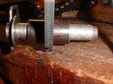 I used 1" thick scrap on the both sides of the DOM and some 1/4" scrap to span the face of the DOM like this to make it perfectly square for welding into position: 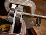 Larry |
|
GuglioLS
Administrator
Jinma354 LE
Posts: 1,276
|
Post by GuglioLS on Feb 1, 2008 0:08:38 GMT -5
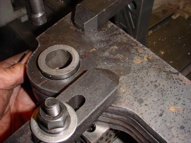
After welding, they came OK and are square:  As you can see from the flash pictures, It's getting late so time to wrap it up for the evening. I test fit the jaws to see how the brackets are going to work out: 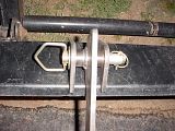 Not to shabby, in fact perfect fit, Between Rob's great design and the decent plasma cuts, It's actually going to work out quite nice  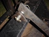 Larry |
|
GuglioLS
Administrator
Jinma354 LE
Posts: 1,276
|
Post by GuglioLS on Feb 1, 2008 0:10:07 GMT -5
Overall shot of what the jaws look like on the bucket. I need to remove that center hook and install a 1/2" plate on top of the bucket to support the grapple and for something thick to weld brackets to.  Closer view of a jaw - It looks sweet. Rob did a great job designing all the parts to put this together.  Larry |
|
GuglioLS
Administrator
Jinma354 LE
Posts: 1,276
|
Post by GuglioLS on Feb 1, 2008 0:11:09 GMT -5
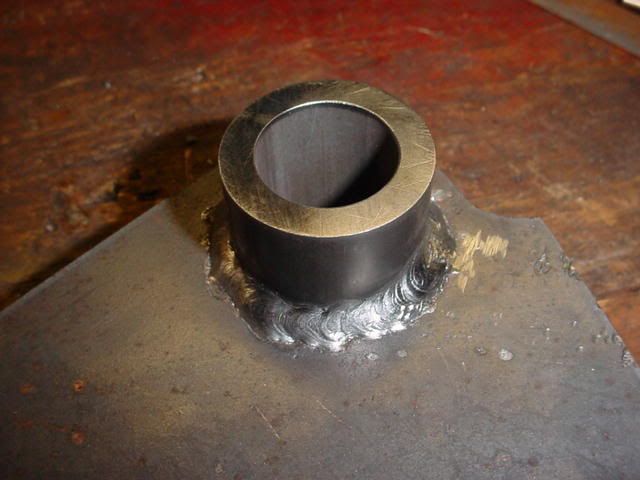
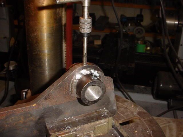
I wanted to add grease fittings to the pivot points for the grapple jaws, so I did. First was to drill through the jaw and seamless tubing: 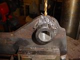 Then tap for a 1/4-28 grease fitting.  Larry |
|
GuglioLS
Administrator
Jinma354 LE
Posts: 1,276
|
Post by GuglioLS on Feb 1, 2008 0:11:35 GMT -5
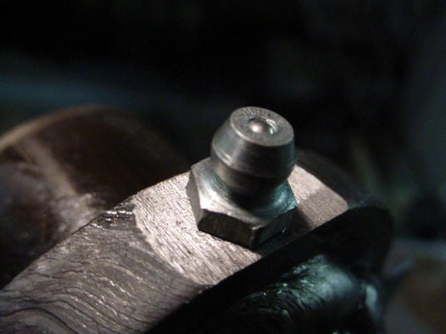
After taping the hole it was time to install the grease fitting: 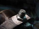 Both done, there is plenty of clearance from the tip of the fitting to the bottom of the bracket. To grease them, the jaws will need to be in the open position - 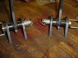 Larry |
|
GuglioLS
Administrator
Jinma354 LE
Posts: 1,276
|
Post by GuglioLS on Feb 1, 2008 0:12:09 GMT -5
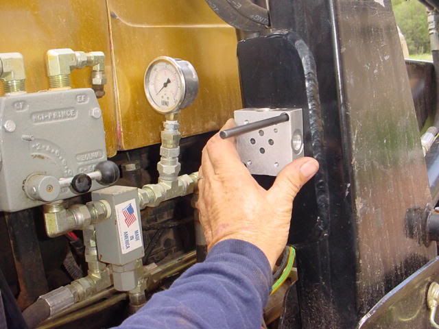
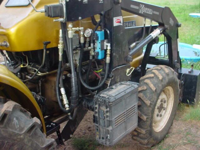
Time to switch gears a little. I figured I better get the hydraulics ready before any more work on the mechanical part of the grapple. So I started to mount the Hydraulic solenoid & Sub-plate. First was to locate a position where the solenoid would fit, be protected yet be close to where it needed to to be connected to the existing tractor hydraulics. I settled on the FEL support post upright. Using a transfer punch the two holes to mount it were located: 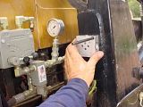 Drilled and taped for 1/4-20 SHCS - 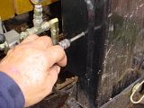 Larry |
|
GuglioLS
Administrator
Jinma354 LE
Posts: 1,276
|
Post by GuglioLS on Feb 1, 2008 0:13:40 GMT -5
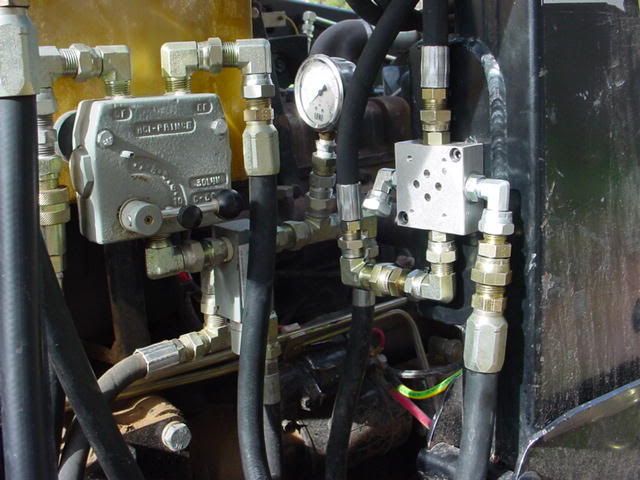
With the holes taped and the sub-plate mounted, time to install some hydraulic fittings. I have a bunch of fittings left over from previous projects. Not all the fittings I have are the ones I need, However with a little creativity, I got most of the connections made with the use of some adapters I had  In the upper left of the photo you may notice that gizmo with the black knob at the end of a handle - that thing is an adjustable hydraulic divider. With that I can adjust the flow of fluid going to the grapple cylinder to control it's speed. Not only that, the grapple will be a true "third function" meaning I can operate the bucket up / down, bucket curl/dump & operate the grapple all at the same time without "feathering" any of the valves. 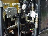 After all the connections were made, it was time to install the solenoid valve onto the sub plate -  The valve is now installed, I think it looks pretty good in this location, is well protected and easy to make the connections -  I need to get some more fittings and hose to complete the hydraulics portion of this project. Larry |
|
GuglioLS
Administrator
Jinma354 LE
Posts: 1,276
|
Post by GuglioLS on Feb 1, 2008 0:15:02 GMT -5
Soon I will need to clamp the grapple jaws to support braces for welding. I will need some pipe clamps, of course I don't have any threaded pipe for the clamps so I had to make that too  After scrounging around the metal pile in skyscraper tall weeds, I found some 3/4" pipe, then proceeded to thread the ends. I've had the clamps for 30 years, but never had a use for them until now. I bet now that I have a set I will find all kinds of stuff to use them on.   Larry |
|
GuglioLS
Administrator
Jinma354 LE
Posts: 1,276
|
Post by GuglioLS on Feb 1, 2008 0:15:54 GMT -5
Oh - almost forgot, all of todays progress was AFTER Esther and I went wood chipping. We filled the trailer over the brim. That chipper is awesome -   Larry |
|
GuglioLS
Administrator
Jinma354 LE
Posts: 1,276
|
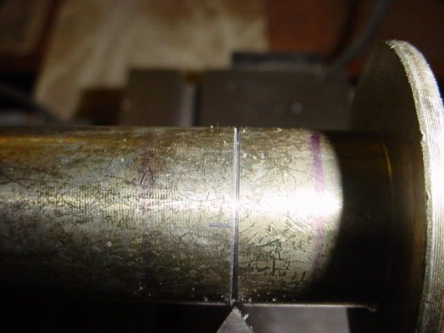
Post by GuglioLS on Feb 1, 2008 0:22:54 GMT -5
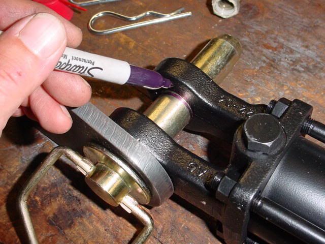
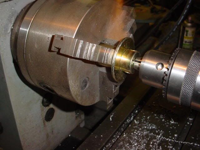
Here is the Pin modification to add grease fittings: First was to mark the pins where the clevis ears are so that a V grove can be cut into the center of the clevis metal -  Crude but effective - 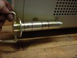 Then I had to pull off the handles so I could turn the pin in the lathe without those handles flopping around off balance - 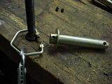 Then chuck up the pin in the lathe and use a center drill - 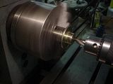 Larry |
|
GuglioLS
Administrator
Jinma354 LE
Posts: 1,276
|
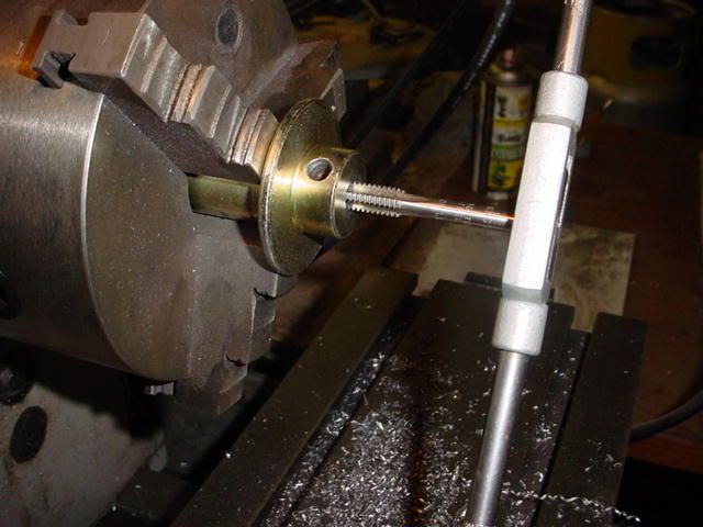
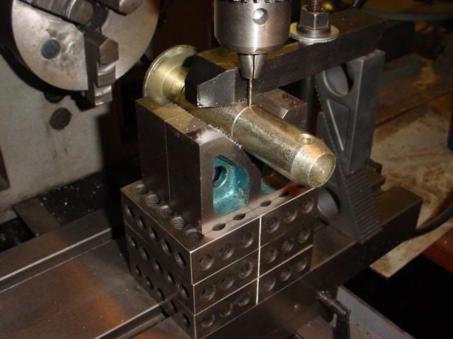
Post by GuglioLS on Feb 1, 2008 0:35:33 GMT -5
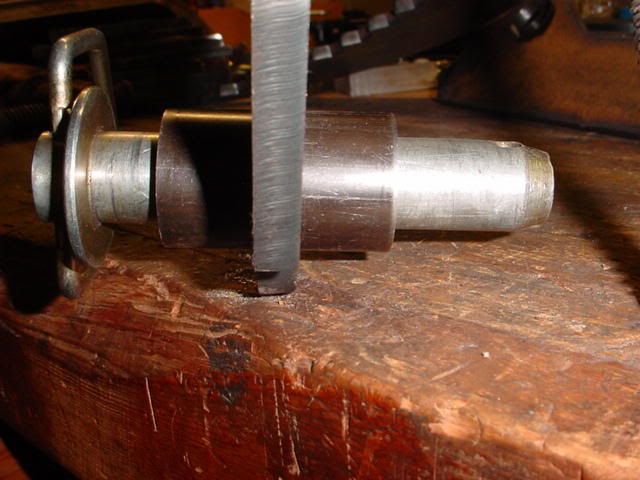
Next was to drill three and a half inches deep into the center of the pin with a letter "F" drill to tap the hole 5/16-18 thread. 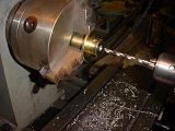 Got the drill buried all the way into the hardened pin -  Next - tap 1/2" deep -  Test fit the set screw, so now I have a captured hole inside the pin - 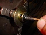 Larry |
|
GuglioLS
Administrator
Jinma354 LE
Posts: 1,276
|
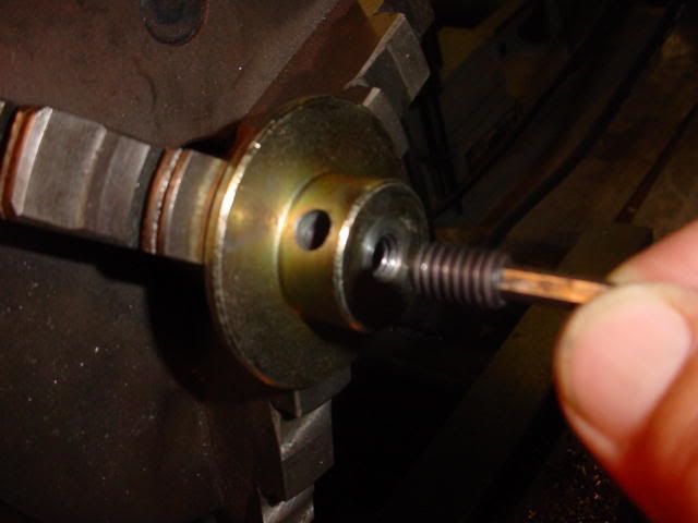
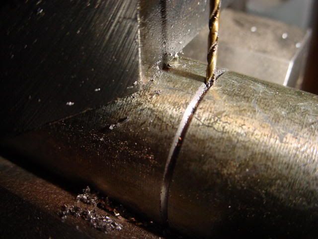
Post by GuglioLS on Feb 1, 2008 0:36:54 GMT -5
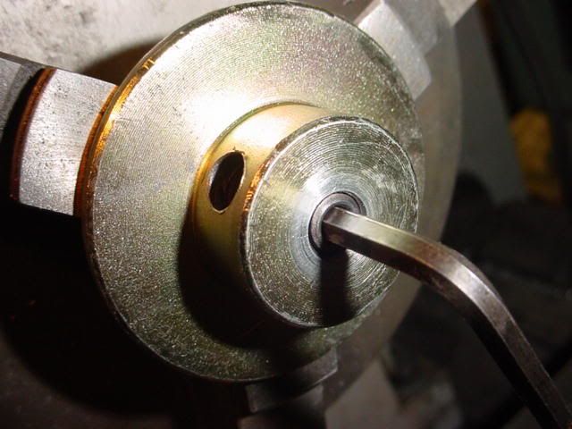
The set screw fits just right, it bottoms out & seals against the end of the internal tapped threads -  Next was to cut a 60* "V" grove into the pin where it rides in the center of the cylinder clevis ears this will allow a channel for grease to completely surround the pin for maximum lubrication - 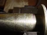 Now it's time to drill .050 holes into the center of the V grove to meet the hole that goes through the center of the pin. I drilled 3 holes around the circumference at 120* angles. 6 holes per pin, 12 .050 holes total. I did NOT break the drill, I ran the spindle at 2800 RPM. 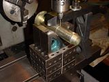 A closer look -  Larry |
|
 I've never done this before, I consulted Rob he said to "index" on the center - whatever that means, then go as slow as possible, so here goes: