GuglioLS
Administrator  Jinma354 LE
Posts: 1,276
|
Post by GuglioLS on Jan 28, 2008 22:50:57 GMT -5
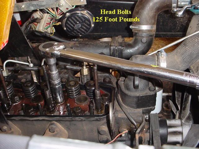
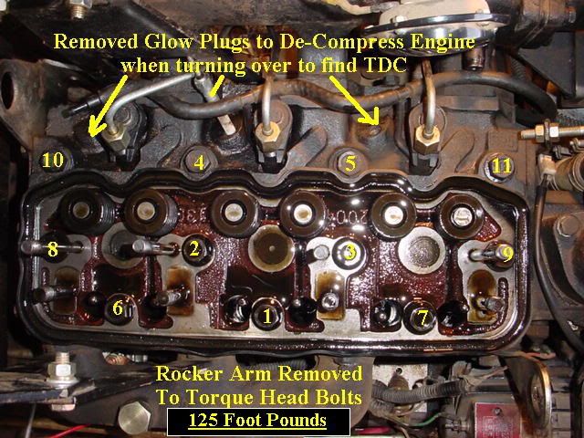
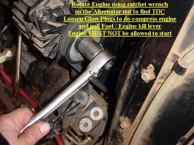
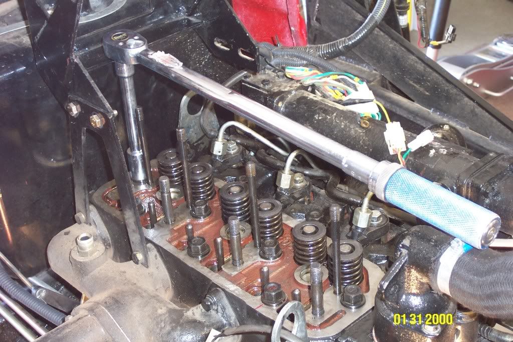
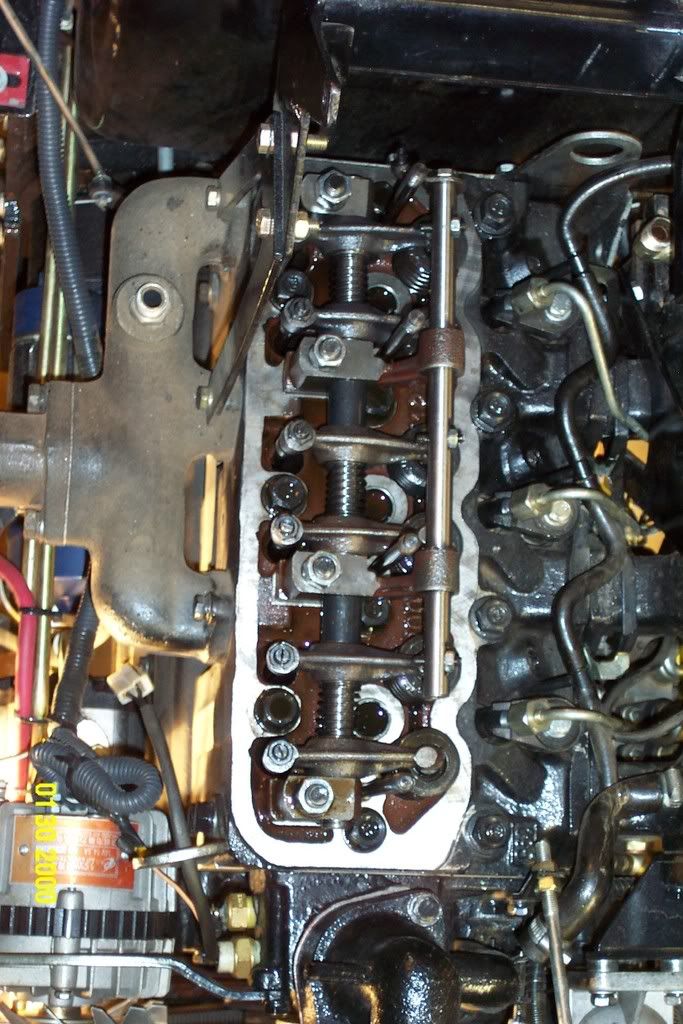
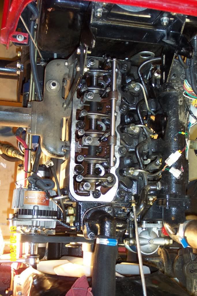
TY395 Valve clearance adjustment and head bolt re-torque procedure. The torque values I posted are what I used on my 2005 TY395 E-3 engine only. I want to make it clear to everyone, that you MUST find the correct values for your particular engine. If you do not have an engine manual, somehow get one, or get a photo copy of one. Do not ever use a value simply because someone "said so".Please feel free to use this as a guideClick on the pictures below to see a full size picture with details. Disconnect the de-compression rod at back of valve cover. Do this by removing the cotter pin and sliding out the pin. Remove the three acorn nuts, washers and rubber seals on top of valve cover. Remove the valve cover to expose the rocker arms, adjusters, and head bolts. Remove the 4 rocker arm nuts by loosening each one a little at a time as the rocker arm is under extreme pressure by the valve springs. Once the 4 nuts are removed lift off the rocker arm assembly and set it aside on a clean surface. Re-torque the head bolts to your engines specs I set mine to ~ 125 foot pounds which is much higher that the manual states. Using the pattern as indicated in the photo. Re-install the rocker arm assembly tightening each nut a little at a time to re-compress the springs and so that is goes straight down evenly and does not bind. I was able to tighten the rocker arm nuts to 65 foot pounds - there is no spec for the rocker arm nuts or bolts. Depending on the hardware installed in your engine 65 Ft/Lbs may be way too much and cause damage. In order to adjust the valve clearance you must find Top Dead Center for each cylinder one at a time. You must keep the engine from starting or even trying to start – Turn off Fuel at fuel bowl, Pull and tie back the fuel cut off, Place transmission in neutral and set the parking brake. If you so desire you can also loosen the glow plugs to de-compress the engine doing this makes it much easier to rotate the engine. Rotate Engine clockwise using ratchet wrench on the Alternator nut to find TDC. 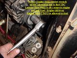 Start with the number one cylinder - the one closest to the radiator. Rotate the engine clockwise while observing the intake valve, when the valve opens then closes all the way you are now at Bottom dead center for that cylinder. Mark the crank shaft pulley with a piece of tape then rotate an additional 180 degrees this will be very near top dead center on the compression stroke. At this point you can now set the intake and exhaust valve clearance for the number one cylinder. Check gap with feeler gauge between rocker and the top of the valve. To adjust loosen the locking nut on opposite side and with a screwdriver turn in or out the adjuster to achieve the proper valve clearance. Once proper clearance is obtained hold the adjusting screw with a screwdriver while tightening the locking nut re check clearance and repeat as needed until the clearance is correct and the locking nut is tight. Now repeat the entire process for the number 2 and number 3 cylinders making sure to find top dead center on the compression stroke for each cylinder. 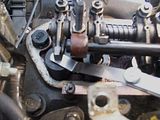 Once complete, replace the valve cover making sure the de-compression assembly fits properly into the decompression rod on the rocker arm assemble. Reattach the decompression rod on the outside of the valve cover and replace the cotter pin. Check for proper decompression lever operation then replace the three rubber seals, washers and acorn nuts on top of the valve cover. Larry |
|
GuglioLS
Administrator
Jinma354 LE
Posts: 1,276
|
Post by GuglioLS on Jan 28, 2008 23:07:26 GMT -5
How to find Top Dead Center (TDC) for adjusting the valves -
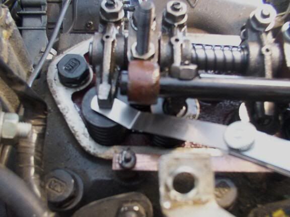
Rotate engine by hand in normal rotation direction. Observe the action of the valves you are working on. You will see the exhaust valve open and then close, as the exhaust valve closes, you will see the intake valve open and then close, the intake closes pretty much at Bottom Dead Center (BDC). At the moment that the intake closes, you will need to rotate the crankshaft 180 degrees to get to TDC. This will be difficult to accomplish as you will be compressing the air in the cylinder, so release the compression, by using a small wrench on the end of the compression release rod or by removing the glow plugs, as I did. Turn the compression release back to the run position, and then adjust both of the valves on that cylinder only. You will actually be able to feel a slight looseness in BOTH of the rocker arms at this point if you grab them and wiggle them. This is the so called Valve Lash. Put the correct feeler gauge in between the rocker arm and the top end of the valve, it should go in with a slight drag, if it won't go in at all or feels sloppy, loosen the lock nut on the other side of the rocker arm, and then turn the adjuster with a screw driver, tighten the locknut down and recheck lash.
This will take a few times to get the hang of it, when both valves on that cylinder are where you want them, move to the next cylinder, resist the temptation for short cuts, verify valve action and feel the compression coming up toward top dead center, then you will KNOW where your are. Rotate the engine several times with compression released as well, and watch valves, this will give you confidence.
TDC, is every time the piston is at the very top most point with the crankshaft pointing exactly straight up,, it is said to be TDC. This occurs once at the end of the compression stroke and Again at the end of the Exhaust Stroke, so it is CRITICAL, that we are sure to find TDC on the Compression Stroke. TDC at the end of the Exhaust Stroke has the Exhaust Valve just beginning to Close and the Intake Valve just beginning to open, so it is obvious you can't adjust the valve lash there. Do Each Cylinder Separately.
Larry
|
|
quikduk
CTW Life Member
 Dog House
Posts: 552
|
Post by quikduk on Feb 11, 2008 19:23:12 GMT -5
I'll add my $.02 here as I, as well as others, here have performed this procedure and hopefully the items I encountered will serve as lessons for others.
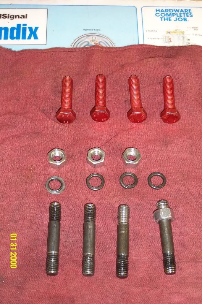
I performed the re-torque and valve clearance adjustment at the 10 hour mark JIC. For the most part, it went as planned. I had some issues with the rocker shaft studs that are noted below. I had to replace the grade-nothing studs and nuts with grade 8 bolts, flat and split washers, not to mention chase all the holes. No big deal but still a P.I.T.A.
I started with the following “pre-flight” procedures:
-hose off the engine and bodywork, then blow off with compressed air to prevent crap from falling into the open engine
-Make sure the keys are out of the ignition
-Battery disconnected
-The tractor is in "Neutral"
-Parking brake engaged
-The fuel is shut-off
-The "Kill" switch is pulled and held back (vice grips)
Two important things to keep in mind:
The first, and possibly the best in terms of workability was to use a 32mm 1/2" drive short socket on the crankshaft pulley nut. It is tight, however you can get to it better from the drivers left side than from the right. It is far easier to turn over the engine here than at the alternator pulley.
The second was that you need a extension handle on the ratchet or a long handled ratchet to be able to turn the engine over. I chose the former by using a piece of 3/4"x1-1/2" .075" wall rectangular tubing I had lying around. You also need to remember to watch the fan blades as some project rearward into the handles "path of travel" more than others.
|
|
quikduk
CTW Life Member
Dog House
Posts: 552
|
Post by quikduk on Feb 11, 2008 19:23:45 GMT -5
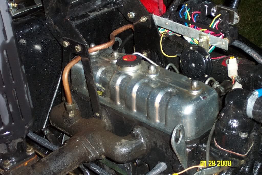
Working on the engine at this time lets you look at how things are mounted or positioned. I found numerous bolts that either didn't have locking washers, were loose or on their way and some even had the wrong size bolts in the wrong locations. I fixed all that I could find while checking that the others were tightened properly and I will continue to do this until I am satisfied that they have ALL been addressed. My 354 (3 cyl) has a reusable rubber valve cover gasket formed to the shape of the valve cover. I was able to reuse it no problem even though I also got a spare in the spare parts box. After this I removed the hood so I could work on it in the garage, since it was getting colder and I have lots of other extra-curricular activities with the family which means the possibility of stopping and starting was very high. My 354 also has the newer emissions certified engine so I had some "stuff" to remove before I could get the valve cover off. I also had to remove the left hood bracket brace to get to the emissions tube fitting on that side which necessitated unbolting the fuse block/relay mount since it shares the bolts with the bracket. 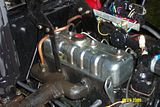 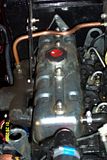 |
|
quikduk
CTW Life Member
Dog House
Posts: 552
|
Post by quikduk on Feb 11, 2008 19:24:48 GMT -5
|
|
quikduk
CTW Life Member
Dog House
Posts: 552
|
Post by quikduk on Feb 11, 2008 19:25:38 GMT -5
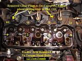
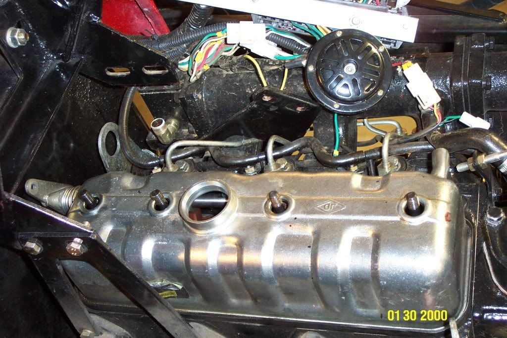
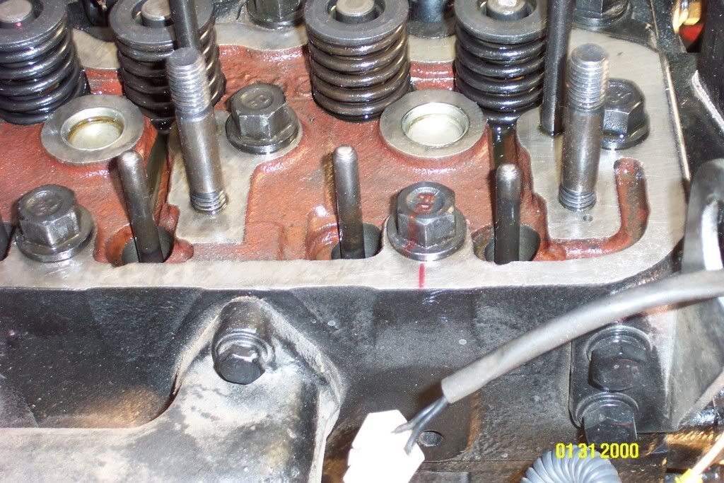
I followed Larry’s procedure outlined above to the letter. I marked the head bolts with a sharpie before breaking them loose so I could measure if the re-torque was tightening them further than from the factory. They all moved about 10-15 degrees further when re-torqued. I felt it was necessary to back off the bolts 1/4 turn or so and then re-torque to spec. to break the initial bolt set and to get an accurate torque value. Once the head bolts were properly torqued, I proceeded to replace the rocker assembly. Here is where I had an issue. I put the rocker shaft assembly back on and tried to get to the 65 ft# required. No go. The studs started to back out around 25ft#. No problem, I will take the shaft off again, remove and clean the studs and then double nut them with blue Locktite into the head so they will hold. Ha! Not only did they keep backing out, two of the nuts stripped themselves and the nuts. I was screwed and really upset now. The darn studs and nuts were grade nothings when they should have been grade 8. Off to Napa I went in search of some replacement studs or bolts. No studs were available, but some nice red-irridite plated grade 8 bolts, flat and split washers were. Some bling for the Jinma. Because of this issue and after talking with Rob, I felt I should chase the stud/bolt holes with a tap. Good thing I did. Talk about crappy thread cutting, but they are perfect now. 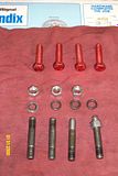 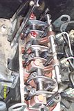 |
|
quikduk
CTW Life Member
Dog House
Posts: 552
|
Post by quikduk on Feb 11, 2008 19:26:40 GMT -5
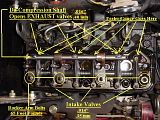
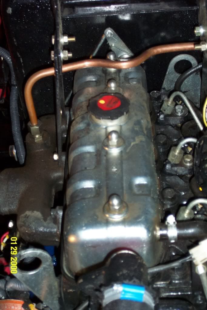
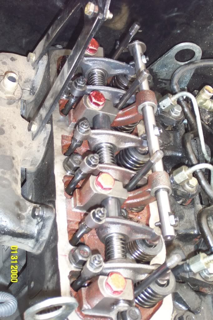
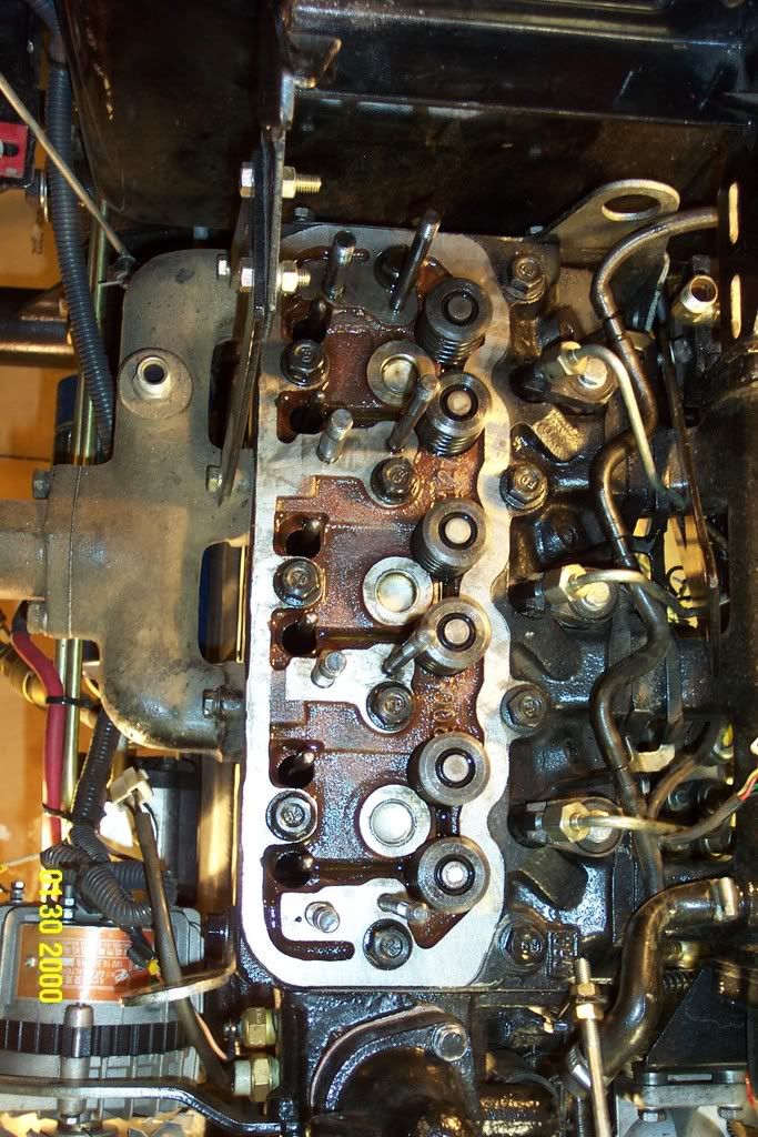
In order to correctly identify the IN and EX valves, (it was very apparent to me which was which from two different viewpoints), I checked the following criteria: 1. I knew that the compression release (de-compression) lever operated the EX valves since that is how they work on every four stroke I have witnessed/owned that had one. 2. The EX valves were very clearly "more directly oriented" towards the EX ports on the manifold and likewise with the IN valves. 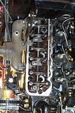 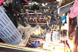 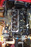 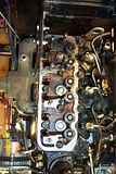 |
|
quikduk
CTW Life Member
Dog House
Posts: 552
|
Post by quikduk on Feb 11, 2008 19:28:16 GMT -5
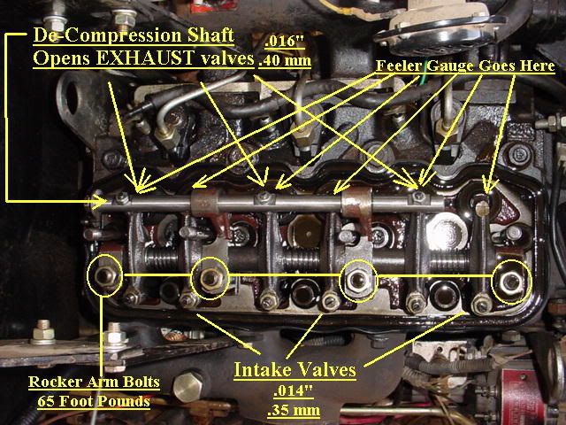
The heads bolts are all now at 125ft#, the rocker arm girdle bolts are all at 65ft# and the valves are at .014 IN & .016 EX. I adjusted them with a firm drag on the feeler gauges, but not grabby. Overall, this was simpler than adjusting the valves on my Ducati. I figured there would be some minor problems, but I am fairly confident I can usually overcome those.
When I finally started it, the engine started easier and revved quicker and since my manual throttle is typ. set at around 800-900 rpm, I noticed that I had to adjust it down a bit since the revs took off up to around 1100 rpm. Once I adjusted it, the engine sounded a bit smoother...for a 3-cyl diesel. Additionally, the engine was easier to rev-up and settled down more quickly. The veterans here know this and after performing this adjustment and witnessing the results myself, I confer and strongly suggest to all "new" Chinese-tractor owners that they get this done as soon as possible. There are too many variables in the way these are assembled to choose otherwise.
|
|
quikduk
CTW Life Member
Dog House
Posts: 552
|
Post by quikduk on Feb 11, 2008 19:29:16 GMT -5
|
|
|
|
Post by duecento on Sept 29, 2015 21:41:10 GMT -5
Even though this is a very old post, I feel obliged to warn other tractor owners that this is a prescription for disaster. 125 ft/lbs is way too high and will likely result in pulled threads in the block. Better fasteners are always a good idea, but upping the torque you put on those fasteners is beyond foolish. If the stock spec is good enough to seal the head gasket, overtightening them gains NOTHING and risks broken expensive part$. The head bolts in a little diesel like these are not very stressed.
Again with the rocker shaft studs: If you are stretching the stock fasteners you are putting way to much torque on them. Once they are tight enough to do the job, nothing is gained by going tighter. The rocker shaft bolts are only lightly loaded so increasing the load carrying capacity has no effect on anything. It is not clear where he was stretching the studs or pulling the threads. Either way, nothing is tp be gained and there are great risks. Just use the stock specs and save yourself a lot of grief.
No matter what he says about it running better afterward, unless he had a leaking head gasket, nothing would have gotten better by doing this, and most likely his performance "improvement" was wishful thinking.
|
|
quikduk
CTW Life Member
Dog House
Posts: 552
|
Post by quikduk on Oct 8, 2015 16:08:02 GMT -5
You are correct in one thing...that this is an old post...because most of us who were part of the original forum group and then moved to this forum are all busy using our Chinese tractors.
I will say that I have successfully built dozens of engines in my lifetime from various rebuilds of street versions to high performance variants and all have without exception worked flawlessly. Now a lot of that is due to experience as well as proper planning but I, as well as others who are far better at mechanical things than I, have put together the best cohesive knowledge base for new and future Chinese tractor owners.
You state that the torque values used are too high for these fasteners? I verified what they "should" have been set at from two successful Chinese tractor dealers as well as from contacting the factory. The cylinder head, in my case, was loose (leaking slightly) from the factory. The gasket didn't need to be removed and either annealed or replaced but rather the head re-torqued. When measured prior to removal, the head bolts were between 118FT/# and 132 FT/#. When compared, averaged and verified, the factory and others queried agreed with the 125Ft/# re-torque value. So far, the head is sealing perfectly.
Re: the valve train rocker stud torque values, the existing head had poorly tapped threads to begin with and the bolts were of unequal temper and torque as well as construction. Their size as well as use allows the higher torque value and while it may have been better to stop between 48FT/# to 55Ft/#, the security of the valve train as well as the equal loaded heights off the head were not accomplished until the torque reached 64.9752Ft/#. I rounded up .0248Ft/#. Sorry.
The smoother running is most likely attributed to the correct valve clearances obtained during this service. What all of us that have had significant experience with these Chinese tractors and implements can attest to is as follows:
1. different Chinese factories make different quality tractors
2. bolts are almost always under-torqued and have a value that does not exactly meet their designated torque requirements
3. the assembly and adjustment of various elements is almost non-existent and local USA dealers have their work cut out for them prior to sale
4. the "fluids" used are significantly sub-par with modern USA/European specs
5. the rubber components all have too little Carbon-Black and no UV stabilizers in them as they rot off within a year or two when exposed
6. the paint used on various components has a significant amount of lead in its base (likely makes it last longer but modifying these tractors definitely requires the use of a proper respirator/filter.
7. Chinese electrical components, construction and quality make the old Lucas electrical systems appear to be sheer genius.
I am sure I could continue to expand on these items and thoughts but likely to no avail. If you want to trust our experience, fine. If not, also fine...but don't assume that we don't know what we are doing nor that we would impart disastrous mechanical suggestions to newbies.
YMMVOC
Regards,
Quikduk
|
|