3RRL
Administrator  Huge Kama
Posts: 2,027 
|
Post by 3RRL on Feb 6, 2008 20:58:28 GMT -5
Well, I just got back from the property and adjusted the Valve Lash on my 55HP Kama 495T2 4 cylinder engine. After getiing some tips from the previous thread, it was quite easy to do. I followed the instruction from my manual as to the routine. It was a good thing because I already have about 185 hrs on the motor and I could never get it to rev up to the rated 2300 rpm. I found that 2 intakes and 1 exhaust valves were way of of spec. After adjusting and re-torquing the heads to spec, it reved up to 2400 rpm easily. This now gives me full range of power band on this powerful 55 HP engine. I'm glad I did it and you should check yours. First some preliminary safety steps BEFORE starting this adjsutment. MAKE SURE the fuel valve is closed. (Click on the thumbnails to enlarge) 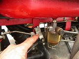 Second, I used a pair of Vise Grips to keep the kill switch pulled back. Also make sure the keys are out of the ignition! You DO NOT want the tractor to start by accident when doing this procedure, so use all necessary precautions. 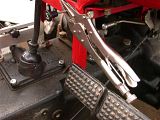 |
|
3RRL
Administrator  Huge Kama
Posts: 2,027 
|
Post by 3RRL on Feb 6, 2008 21:00:15 GMT -5
Ok, now locate the decompression lever and cable. It is located towards the rear of the valve cover near the firewall. There's a cable that attaches to the lever via a cinch bolt. When my tractor was delivered, this cable was not hooked up. The new 4 cylinder engines start so easily that there is no need to use the decompression feature when starting. I hooked mine up anyway in so I could crank some oil in the bearings and journals on cold days, but nevertheless, it always started right up on the first crank even without using it. 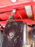 To take off the decompression cable from the decompression lever, loosen the nut and remove the cinch bolt and wire cable from the decompression lever. 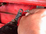 |
|
3RRL
Administrator  Huge Kama
Posts: 2,027 
|
Post by 3RRL on Feb 6, 2008 21:01:49 GMT -5
Next, take out the bolts that hold the decompression lever to the valve cover. This takes a 10mm wrench. Note that you can remove the lever without taking off the cable, however, upon re-assembly, I found it much easier to align than with the cable still attached to the decompression lever. (Learning curve ;D) 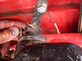 Then you can pull/pry off the decompression lever from the valve cover. Note in this picture that the decompression lever has a slotted key that fits into the end of the decompression rod. That is why you will need to re-align the lever upon assembly later. 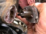 |
|
3RRL
Administrator  Huge Kama
Posts: 2,027 
|
Post by 3RRL on Feb 6, 2008 21:04:01 GMT -5
OK, well now you can remove the valve cover. Use a 13mm socket to unscrew the Acorn nuts and remove the washers. DO NOT store them in a place where you can't find them later, like I did! Dang! 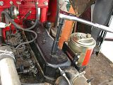 Then you can pry off the valve cover. Since the decompression lever is already off the valve cover, lift it straight up off the anchor bolts. This is a shot of the pushrod side and shows the exhaust manifold. Each cylinder has an intake and exhaust valve. The valve nearest the exhaust manifold exit is the exhaust valve and the other is the intake valve. On this engine, the intake valve on number 1 cylinder is the first one nearest the radiator. The valve next to it is the number 1 cylinder exhaust valve. 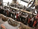 |
|
3RRL
Administrator  Huge Kama
Posts: 2,027 
|
Post by 3RRL on Feb 6, 2008 21:10:23 GMT -5
This photo is from the valve side of the engine where the fuel injectors are. Towards the right of the photo is the radiator (not shown) and towards the left is the firewall. So number 1 cylinder is nearest the radiator to the right. 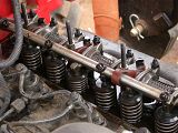 My engine manual specifies the settings in Metric (everything) so the first thing I did was convert to English (everything) That is for all fluids, hp and torque ratings, lift capacities, tire pressure, relief valve pressures, weight...everything. It's good to know these things anyway. My book tells me to set the intake valve between .010" to .014" and the exhaust between .012" to .016". I went to the middle of each setting, choosing .012" for the intake valve and .014" for the exhaust valve. I am NOT a mechanic so you'll have to ask one why it's better to set at the low or high of the tolerance. I choose the middle, figuring this can't be TOO bad. |
|
3RRL
Administrator  Huge Kama
Posts: 2,027 
|
Post by 3RRL on Feb 6, 2008 21:13:09 GMT -5
Next thing I did was to tighten my alternator belt so I could use the nut on the end of it to rotate the crankshaft around. This step can be done anytime after the first safety steps...I chose to do it here. First, loosen the bolt for the sliding bolt on top of the alternator support bracket. I think it takes a 13mm wrench. 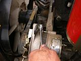 The alternator has 3 attachments, 2 of them are for the top bracket. I had to loosen the bolt that holds the bracket to the engine block so the thing would slide on the first bracket. this took a 15mm socket. 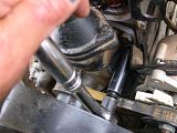 Then, I loosed the bottom pivot with a 15mm wrench and socket. Then I got a pry bar and tightened the alternator belt. No pic for that one, I only have 2 arms. I tightened it so there was about 1/2" of play when you press REALLY hard on the belt so I would not have to slacken it later. I ended up using the fan blades to help rotate the crankshaft along with turning the alternator with a wrench with the decompression bar holding the valves open. Here is the bottom pivot bolt. 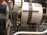 |
|
3RRL
Administrator  Huge Kama
Posts: 2,027 
|
Post by 3RRL on Feb 6, 2008 21:14:52 GMT -5
Next step is to rotate the crankshaft so you can "see" the valves working. Note the direction of the fan blades to determine which way to rotate the engine. On my 495T2 motor, when standing in front of the tractor, facing the rear, it rotates clockwise. From in the cab it would rotate counter-clockwise. I also noted that on this engine, the decompression bar activated the exhaust valves. Ok, so now you want to start rotating the crankshaft to see the valves working and find "top dead center" of number 1 cylinder. First, use the decompression lever, stick it into the end of the rod to decompress the cylinders. Then start rotating the crankshaft. 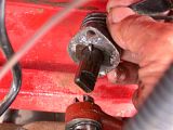 Watch the number one cylinder valves. When the intake valve shuts, rotate the crankshaft another 180° to get it to TDC. But first, mark the crankshaft pulley (I used blue tape) so you know when it's rotated 180°. Then release the decompression rod for doing the adjustments. 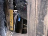 |
|
3RRL
Administrator  Huge Kama
Posts: 2,027 
|
Post by 3RRL on Feb 6, 2008 21:16:23 GMT -5
My engine being a 4 cylinder, is a little different but much easier to do than the 3 cylinder engines. The manual says once you get TDC of number 1 cylinder, you can adjust BOTH intake and exhaust valves of THAT cylinder (#1) In that same position, you can adjust the INTAKE valve of #2 cylinder and also the EXHAUST valve on #3 cylinder....makes it pretty easy. So before I adjusted anything, I did some checking first. Some were good, some were not. 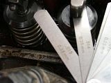 Then I proceeded with the adjustments as outlined in my manual. I've gotten pretty good at reading "Chinglish". Loosen the nut on the screw that makes contact with the pushrod. Then adjust the screw with a screwdriver while holding the nut with a 13mm wrench. What I did was slide the correct feeler gauge back and forth while screwing until I could feel slight friction on it. I held the screwdriver as tight as I could and tightened the nut very tight. Then I checked again to be sure it was the same friction. Being a mold maker, I have calibrated eyeballs and friction thimble thumbs for a very sensitive feeling. 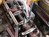 |
|
3RRL
Administrator  Huge Kama
Posts: 2,027 
|
Post by 3RRL on Feb 6, 2008 21:21:30 GMT -5
I was saying how easy it was to adjust the 4 cylinder engine. To adjust the other valves now, activate the decompression rod once again and rotate the crankshaft 360°. That puts number 4 cylinder at TDC...very easy.... Now release the decompression bar again and in this position, you can adjust BOTH intake and exhaust valves on number 4 cylinder (just like you did on #1). You ALSO adjust the exhaust valve on #2 cylinder and the intake valve on #3 cylinder in this position. That's it...you're done adjusting. No more rotating necessary for the adjustment. If you want, you can rotate more and re-check the adjustments just to be sure they meet your approval. Before you re-assemble the valve cover, this is a perfect time to check the head bolt torque. I did not crack mine and remove, rather checked to see if I needed to torque them up. Also take a razor blade and scrape off any old gasket material. Thoroughly clean the sealing edges on the valve cover, the engine block and also the decompression lever gasket. If you have new gaskets (a good thing) then put them on with a little RTV sealer. I did not have a new gasket so I put on a layer of Automotive RTV sealer and let it dry for about a ½ hour. Checked it after popping out 20 buck brush trees and NO leaks!...Very Happy. 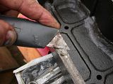 Last, before putting the valve cover back on, take the decompression lever and bolt it VERY loosely to the end of the valve cover. This is important. If you put the valve cover on without it in place, it will not go into its hole on the valve cover because part of it hits the firewall. By having it partially on the valve cover, it fits. Then put the valve cover on completely and tighten it up. Last, wiggle the decompression arm until the key fits into the bar and push it into position. Bolt it up tight too. 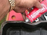 |
|
3RRL
Administrator  Huge Kama
Posts: 2,027 
|
Post by 3RRL on Feb 6, 2008 21:23:07 GMT -5
One last thing, like I said, this is a perfect time to re-torque the head bolts before putting the valve covers on. My manual did not convert well, I think the torque values were transposed or something. But from my past experience, I figured somewhere between 100 to 110 lbs/ft would be adequate. I checked with my torque wrench and they were all in excess of that, so I did not need to do anything there. Overall, after my couple of "learning curve" episodes, it took me just under 1-½ hours to complete. It was much easier to do than I thought. The results were BIG for me, since I told you I could not make 2300 rated rpm before...never really needed it though, with this tractor. However, I was pleasantly surprised that when I pulled the throttle valve all the way, she went right to 2400rpm. That's what I'm talking about! I took it for a test spin with the 1200 lb. backhoe and old lady sitting on it. My Kama 554 weighs in fully loaded around 7,500 to 8,000 lbs (with operator and passenger, loaded tires, wheel weights, FEL and backhoe.) We went up the hilly road in 2nd high at 1500 rpm without even a hint of bogging down. That was really rewarding...because before, it would start to bog a little at that rpm or more, so I'd have to kick the old lady off to make the grade...Ha ha..just kidding.  But it ran a lot better, cooler and stronger, so I'm VERY happy with the result. I recommend each of you do your valve lash adjustment at the suggested intervals...it makes a difference....and oh...don't smash your thumb like I did. |
|
3RRL
Administrator  Huge Kama
Posts: 2,027 
|
Post by 3RRL on Feb 6, 2008 22:30:26 GMT -5
Update on the RTV sealer I used for gasket material...don't use it. After about 40 hours of working the tractor in the searing heat, I noticed the valve cover has started a small leak. If you remember, I used RTV sealer to make a gasket. Apparently part of it has blown out and it needs to be replaced. With that in mind, I'm NOT going to recommend using RTV for that valve cover gasket. I'm going to buy some gasket material and make one next time I'm up. I went to the local Napa store to buy gasket material for the valve cover before Labor day. I took it to camp and made up a couple of new ones to replace the crummy RTV I put on. After removing the decompression lever and valve cover, we had to clean off the old RTV crud. Loretta did an immaculate job. she is really good at the small details and has that certain level of tenacity that it takes to do a perfect job. 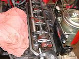 This is the head after I cleaned it off. 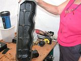 |
|
3RRL
Administrator  Huge Kama
Posts: 2,027 
|
Post by 3RRL on Feb 6, 2008 22:34:02 GMT -5
Then I had to make the new gasket and it was a lot easier than I thought. I cut around the perimeter of the valve cover. 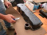 Then I cut the inside of it out by following the inside width of the valve cover. I used a razor blade and it came out pretty good. 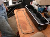 Then I made a new gasket for the compression relief lever. I punched the screw hole clearances in it. I ended up using an old ejector pin sleeve that I ground a sharp edge on and used it like a punch. 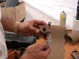 After that, I fit both gaskets into position and tightened everything down again. Did a "visual" check to be sure I could see gasket material all around the outside and fired her up. No leaks at all....pretty happy now. I immediately went over to dig some big holes for the solar trackers and after 2 hours of constant running in the heat, still no leaks....not even a drip!! I did my at 150 hrs but I now recommend to do it right away anytime after delivery or after putting a few hours on the motor. It appears the valve lash might not be set correctly from the factory in all cases and I don't think it is done during (part of) dealer prep. So it's best to do it right away or after a few hours run in. It wouldn't hurt to re-torque the head bolts either. My manuals recommend doing it every 250 hours of use. Rob- |
|
GuglioLS
Administrator  Jinma354 LE
Posts: 1,276
|
Post by GuglioLS on Feb 6, 2008 23:30:51 GMT -5
Hey Rob,
Great write up on your valve lash adjustment. So you got 100 more RPM's out of it? - cool.
The new gasket you made came out perfect, better than OEM I'm sure.
You mentioned the ability to adjust the intake and exhaust on the # 1 cylinder as well as being able to adjust a few other valves so long as the #1 cylinder was at TDC. Thats exactly what my Komatsu dozer manual says to do. That makes it go much quicker.
Great post Rob -
Larry
|
|
|
|
Post by grohgreg on Feb 8, 2008 8:24:11 GMT -5
When I performed this maintenance on my KM454, I didn't remove the decompression lever from the valve cover, but I did remove the cable from the lever. Then I rotated the lever to the point where it slid straight up off the decompression rod. Valve cover came with it. To reinstall, the decompression rod gets rotated into decompression position, which aligns the end tab vertically. Rotating the lever again permits tab and slot to line back up vertically, and the valve cover drops right back in place. No need to bust knuckles between the lever and the fuel tank that way.
It took very little time to realize that the engine manual wasn't written to consider the direct injection head. I could not re-torque head bolts without removing the valve train, and there were 11 head bolts instead of the 8 depicted in the manual. As such, I sorta had to make up my own breaking/torquing sequence. Then I reinstalled the valve train and moved on to the valve lash adjustment.
There's a set of timing marks on the flywheel. They made finding TDC a whole heckuvalot easier. They're under a small inspection port on the upper right side of the bellhousing. But there's no zero. So I centered at the 1 degree mark, then turned the crank till the #1 intake achieved max gap. The rest was dead simple. Only one 240 degree rotation of the crank, and I had all six valves adjusted.
I too cut my own gasket out of bulk NAPA stock, I used the dark gray impervious stuff. Made one for the fill/vent while I was at it. But I did use some silicone to affix the valve cover gasket to the valve cover. Once adhered, I dropped the cover in place - gasket and all. Next time I remove the valve cover, the gasket will come with it.
But before that, I also adjusted the decompression screws. As set by the factory, it took two hands to pull the cable all the way out. By backing them off ever so slightly, they still open the exhaust valves - but are no longer fighting as much valve spring tension. Since exhaust travel is only 0.8-1.2mm. each screw should be adjusted to open its associated exhaust valve 1.0mm. Cable pulls a lot easier now, and decompression is no less effective.
//greg//
|
|
3RRL
Administrator  Huge Kama
Posts: 2,027 
|
Post by 3RRL on Feb 8, 2008 10:11:18 GMT -5
Larry,
Yeah, being a 4cyl allows that kind of adjustment. Sure made it easy and quick.
Greg,
Thanks for adding that information to this thread.
And welcome to the board. I'm sure you'll enjoy this one for a change.
My decompression cable was not attached to the lever when I got the tractor. My dealer (and others) said these engines start so easy and reliably they just stopped hooking them up and indeed mine does. Nevertheless, I hooked it up and it works fine. I use it for a sort of pre-lube to get oil in between the journals and bearings before the shock load of the pistons firings. And only for the first start of the day.
You can see the oil pressure start to build up.
Rob-
|
|