GuglioLS
Administrator  Jinma354 LE
Posts: 1,276
|
Post by GuglioLS on Feb 1, 2008 0:38:10 GMT -5
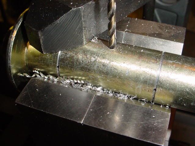
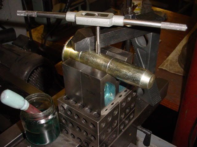
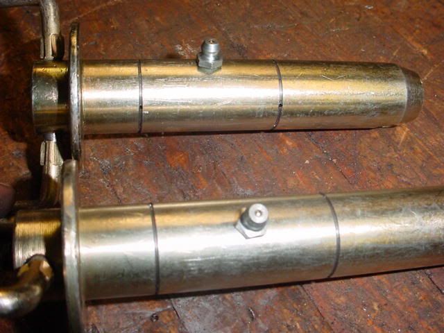
After all that, a hole for the grease fitting is next. I used a 7/32 bit 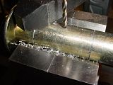 Then tapped for a 1/4-28 grease fitting - 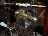 Looks Good - 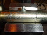 Of course now it wont insert through the bracket or the clevis   Larry |
|
GuglioLS
Administrator
Jinma354 LE
Posts: 1,276
|
Post by GuglioLS on Feb 1, 2008 0:39:17 GMT -5
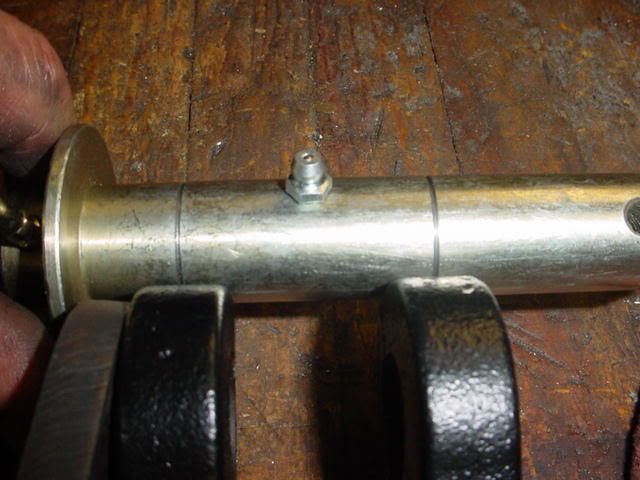
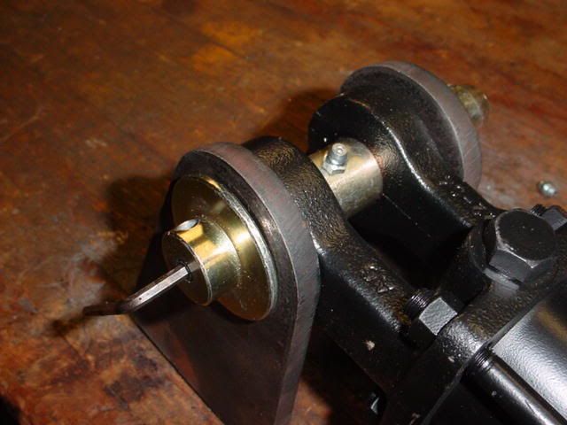
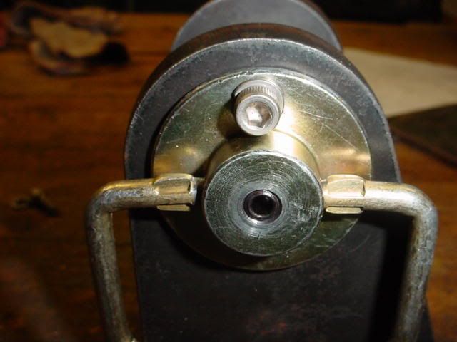
This is how the V grove lines up to the center of the clevis ears- 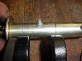 Here are the two sets of pins -  After removing the grease fitting, I was able to install the pin, then re-install the Zerk fitting - this will work.  One last thing to machine on the pin and that is to "move" the hole where the lynch pin goes through closer to the cylinder bracket to keep the pin centered in place. Doing that will keep the V groves centered for maximum lubrication. Larry |
|
GuglioLS
Administrator
Jinma354 LE
Posts: 1,276
|
Post by GuglioLS on Feb 1, 2008 0:39:56 GMT -5
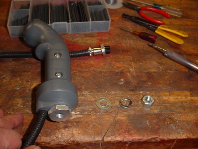
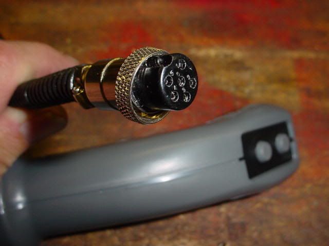
My Really Cool looking two button joystick handle to operate the grapple & FEL arrived from Canada today  The first thing I did was to install a connector onto the end of the cable. I am planning on making a small junction box to plug everything into. 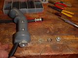 I like it -  Larry |
|
GuglioLS
Administrator
Jinma354 LE
Posts: 1,276
|
Post by GuglioLS on Feb 1, 2008 0:40:32 GMT -5
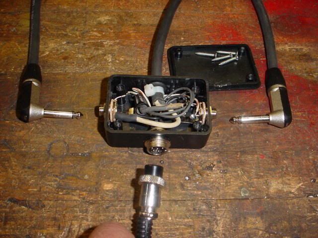
The handle comes standard with two feet of wire. I purchased the 6 pin connector from an electronics supplier then installed it onto the end of the cable:  Then I made up this junction box that everything will plug into. (Two Solenoid cables, The Joystick cable connector, and the + power and ground):  Larry |
|
GuglioLS
Administrator
Jinma354 LE
Posts: 1,276
|
Post by GuglioLS on Feb 1, 2008 0:41:29 GMT -5
Here is the junction box completed and all the cables and connectors plugged it: 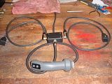 Whenever a switch is used on a solenoid, or any type of inductive load (coils of wire wrapped around a ferris metal core) with DC (Direct Current) You REALLY should install a diode across the solenoid to protect the switch contact from arcing. A diode will short out the resultant reverse current generated by the coil when the switch is opened, (It prevents arcing across the switch contacts extending switch life). So here is the Diode I added to the solenoid connector. One diode per solenoid coil. Make sure the polarity is correct! i.e. The white band on the diode is connected to the + side of the coil. I used a 2.5 amp 1000 volt diode (NTE125) 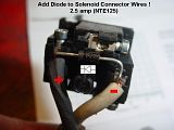 Larry |
|
GuglioLS
Administrator
Jinma354 LE
Posts: 1,276
|
Post by GuglioLS on Feb 1, 2008 0:42:21 GMT -5
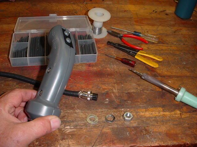
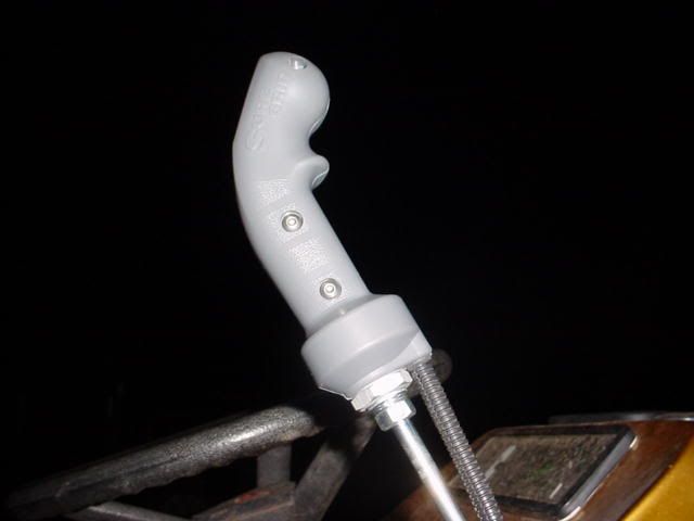
I ordered the handle with a 10 mm X 1.5 mm thread pitch bushing so it would screw right onto my existing FEL valve joystick lever -  Here is the front view:  And a side view, man is this thing ever comfortable! 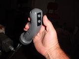 Next is to............ well what is next? Larry |
|
GuglioLS
Administrator
Jinma354 LE
Posts: 1,276
|
Post by GuglioLS on Feb 1, 2008 0:43:36 GMT -5
OK back to work - I made a little more progress on the grapple. I figured that as long as I made those fancy grease-able pivot pins I better lock them in place so the pins wont rotate inside the brackets. First was to drill through the pin shoulder & bracket:  Then tap the hole: 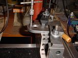 Larry |
|
GuglioLS
Administrator
Jinma354 LE
Posts: 1,276
|
Post by GuglioLS on Feb 1, 2008 0:44:07 GMT -5
Then screw in a stainless steel socket head cap screw (SHCS)  The screw is only 1/2" long so it's flush with the other side of the bracket:  Larry |
|
GuglioLS
Administrator
Jinma354 LE
Posts: 1,276
|
Post by GuglioLS on Feb 1, 2008 0:45:01 GMT -5
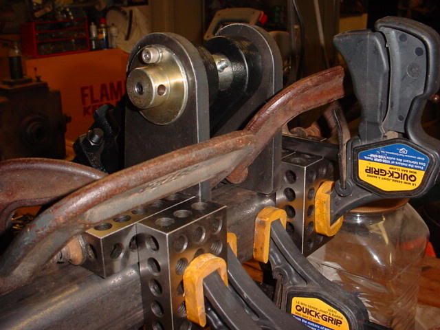
I hope to do some welding this weekend, so I better get busy clamping things together. 1-2-3 blocks came in real handy to get the cylinder mount bracket nice and square onto the 2" square cross tube:  I used a few clamps to get the blocks square to the tube, then clamped the brackets to the block: 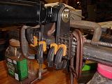 Once everything was square and tightened down I was able to remove all but the essential clamps & 1-2-3 blocks: 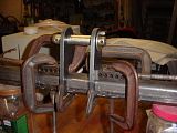 Larry |
|
GuglioLS
Administrator
Jinma354 LE
Posts: 1,276
|
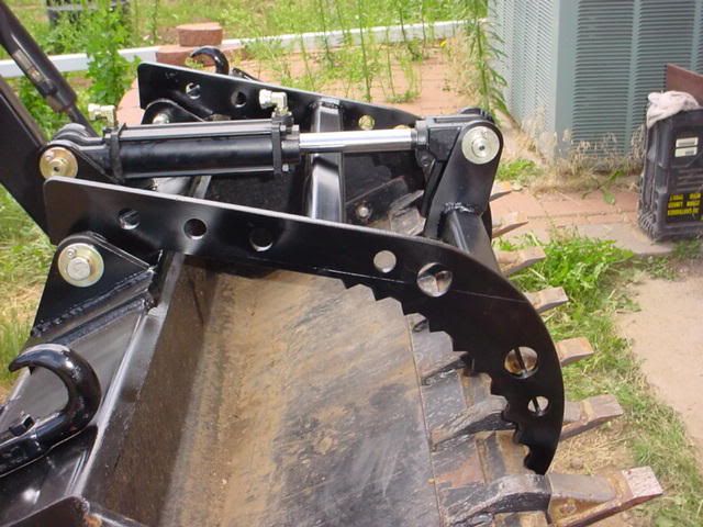
Post by GuglioLS on Feb 1, 2008 0:46:02 GMT -5
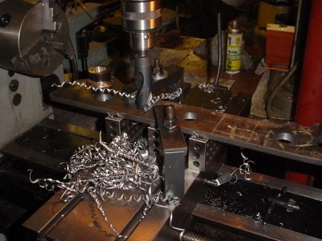
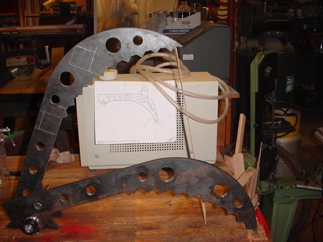
I have a few more minutes before passing out for the evening, so I decided to implement Rob's last minute design enhancements. First was to layout all the locations for some holes, clamp the jaw to the cross-slide, then use a hole saw to cut out a 1.5" hole:  A hole saw is pretty crude but makes a big hole in a hurry. I chased the rough hole with a boring bar to clean up the sides nice and smooth:  Then I drilled out a bunch of 1" holes:  This is the result of all those holes:  In the background just behind the jaws is a printout of what Rob though would look cool on the grapple jaws. What would have taken 5 seconds on the plasma cutter took me 5 hours by hand - I think it was worth it. What do you think?  Larry |
|
GuglioLS
Administrator
Jinma354 LE
Posts: 1,276
|
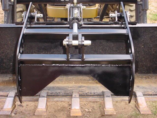
Post by GuglioLS on Feb 1, 2008 0:46:39 GMT -5
I got the Front cylinder bracket welded to the 2" square 1/4" wall cross tube. 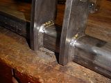 It came out nice and square and just enough room to fit the cylinder clevis without binding. Larry |
|
GuglioLS
Administrator
Jinma354 LE
Posts: 1,276
|
Post by GuglioLS on Feb 1, 2008 0:47:10 GMT -5
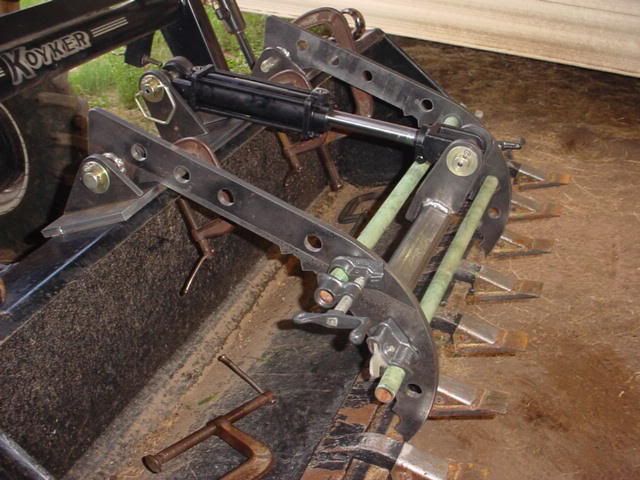
Next was to clamp everything together. Pipe clamps were inserted through the 1-1/2" holes that Rob made me bore out for looks - they sure did come in real handy for clamping.  Another view:  It starting to take shape and it fits EXACTLY like Rob's plans No really, that does not surprise me in the least. I have so much confidence in his design I just blindly put it together, all I had to do was to make sure and lay everything out according to the dimensions of his design. Larry |
|
GuglioLS
Administrator
Jinma354 LE
Posts: 1,276
|
Post by GuglioLS on Feb 1, 2008 0:47:47 GMT -5
I made sure there was no interference by manually moving the grapple jaws from open to closed. Also making sure the cylinder was making full travel completely open & hitting the stops at the pivot end of the jaws and completely closed where the jaw tips would contact the bucket lip. It all fits PERFECT !  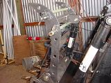 Then I tack welded everything together. 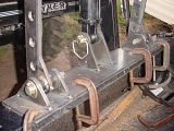 Next is to connect the hydraulic lines to operate the jaws under their own power. That will be done to make sure it moves by itself and to verify all operates smoothly before welding complete beads all the way around. I was messing around with house routing, hose length, fittings, brackets, quick connects for quite a while. I think I am getting close to figuring that part of it out. Larry |
|
GuglioLS
Administrator
Jinma354 LE
Posts: 1,276
|
Post by GuglioLS on Feb 1, 2008 0:48:49 GMT -5
I had a little time to work on it again late this evening. I finished welding all the Jaw parts together and primed it. It looks fantastic! Check it out - 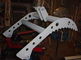 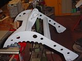 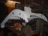 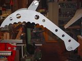 Larry |
|
GuglioLS
Administrator
Jinma354 LE
Posts: 1,276
|
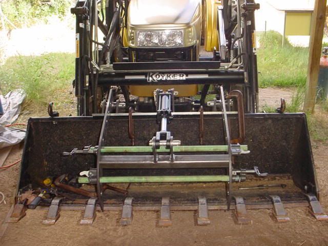
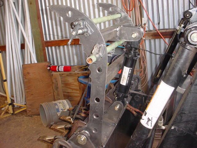
Post by GuglioLS on Feb 1, 2008 0:50:17 GMT -5
After finishing all the welding on the brackets and reinforcements on the top and back of the bucket it got primed and painted -  After the paint dried, the Jaw assembly was then mated & pinned to the bracket assembly. After all that welding, everything was still in alignment as the pins slid right in. Next was to install the cylinder and make sure it still has the proper travel, it does, so no adjustment was needed.  Side view -  Larry |
|