3RRL
Administrator  Huge Kama
Posts: 2,027 
|
Post by 3RRL on Dec 12, 2009 12:22:06 GMT -5
Hi guys, I've decided to tear the 554 Kama apart to deal with the excessive blow by I've had since about 500 hours on the machine. You might remember me trying several things to reduce (and hide) it in related threads here: Re-Route Breather Vent Kama 554I've got 718 hours on the clock, but in reality because the way my hour meter works (via rpm's not time), it's probably got easily over 1,000 hours on it. I've had the Kama since 2005 and have used it for almost every aspect in building my log home and maintaining/improving the 27 acres of Oak forest. The 1000 hour maintenance schedule calls for removing the head and cleaning off all the carbon build up so I decided to do that and get to the bottom of the blow-by problem. I've got a few photos to share and show what's going on. Most importantly, to help with re-assembly later on because I don't have an engine parts manual. This is going to be an "In Frame" engine overhaul. First was to remove the hood for better access. Then start taking things off one by one. Before removing, I marked every component so they go back in the same place. 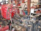 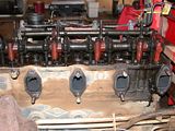 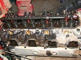 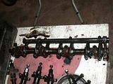 Since I started a couple weeks ago, taking my time, I've been in touch with Chip at Artrac for advice and ordering new parts from him. He has been a gold mine of information for me. Rob- |
|
3RRL
Administrator  Huge Kama
Posts: 2,027 
|
Post by 3RRL on Dec 12, 2009 12:56:50 GMT -5
|
|
3RRL
Administrator  Huge Kama
Posts: 2,027 
|
Post by 3RRL on Dec 12, 2009 13:18:40 GMT -5
You will see there are no cross hatchings left and there was a good size "ridge" formed at the top of each liner. I had bought a new set of rings and valves from Chip about a year ago when I first started having the excessive blow by problem (fearing the worst). So I was able to install a new ring into the cylinder bore and measure the gap of the ring. It was in spec at the top of each liner, but below that, the gap got really big ... way out of spec. I had this condition on 2 cylinders. The other 2 were at the very end of the gap tolerance. After rotating the crank, I checked out each one. But before I could see what shape the rings were in, I'd need to drop the oil pan and remove the connecting rod bolts so I could pull out the pistons. Of course that meant removing the front drive shaft first. Here are some photos (below) of what it looks like in there from underneath with the oil pan removed. You can also see the crankshaft, oil pump suction screen and then the pump itself. 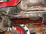 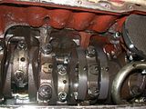 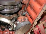 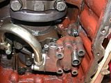 Up above the oil pump, where the spiral drive gear is, you can see the camshaft lobes. Unfortunately I couldn't get a good photo of that. |
|
3RRL
Administrator  Huge Kama
Posts: 2,027 
|
Post by 3RRL on Dec 12, 2009 13:35:44 GMT -5
The next step was to remove the connecting rod bolts and remove the pistons. As always, my dear wife Loretta was there to help. She was "above" and I was underneath the tractor. I must say what a helper she's been in all the mods and repairs I've done. You can't imagine how frustrating and exhausting it gets having to crawl underneath and then get out above over and over again. She pulled out the pistons one by one as I pushed them up. Prior to that, I had marked the connecting rod upper and lower half and also (next to) the bearing journals so that they would go back in the same place and same orientation. Note that in the third photo below, I finally found the culprit that was behind the excessive blow-by all along. It was a cracked #1 ring (shattered) on piston #3. Note also that the ring groove on the piston was about twice as wide as it should be. The last photo shows the engine block without pistons in it. 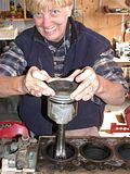 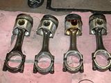   |
|
3RRL
Administrator  Huge Kama
Posts: 2,027 
|
Post by 3RRL on Dec 12, 2009 14:05:57 GMT -5
The last thing I had to do before ordering new parts from Chip was to remove the (wet sleeve) liners. They came out pretty easy by tapping them out from the bottom with a copper bar. Once the head was exposed, I used a couple of small pry bars to get them out. So the photos below show them coming out and what the engine block looks like with the liners removed. Note the 2 "O" rings on the bottom of the liner sleeve. There was no "O" ring on the top or under the head of the liners. 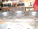  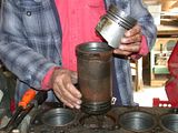 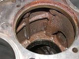 At first I was afraid that the liners would not come out easily. Since it was really cold in the barn, I used a heater that Larry G gave me to cure heat shrink tubing for the electrical kit he gave me. I put the heater all around the water channels on the block, hoping it would expand the block slightly. It definitely heated up the block and seemed to help with getting the tight liners out. So now I'm stuck with a bunch of clean up to do. I've got engine parts all over the barn. I've also got some photos of removing the valve springs and cleaning the head, but they are still in my camera in the barn. I'll follow up next week with an update. Rob- 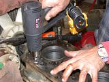 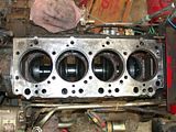 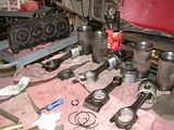 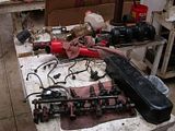 |
|
3RRL
Administrator  Huge Kama
Posts: 2,027 
|
Post by 3RRL on Dec 12, 2009 19:22:50 GMT -5
I had time to upload these photos of the overhead valve spring compressor I bought at Harbor Freight. I was going to make one, but after seeing it there and for very little money, I thought I'd give it a try. After all, I'm by no means a mechanic so for this one time it seemed to fit the bill.   It was pretty easy to use. The fingers are of unequal length. You insert them under the lowest spring coils and start turning the knob. Make sure the fingers remain under the coils and also make sure the compressors under the handle do not cover the little spring keepers. After you've turned it all the way down compressing the spring, the 2 little keeper halves can be removed from the retainer. I used a little magnet to get them out. Now you can take the spring off and release tension on the tool. Then flip the head over to slide the valves out.     You can see the exhaust valve is covered with carbon deposit. But none of the valves were burned so I plan on reusing them. I marked each one and the head so I know where they go. After cleaning out as much crud and deposit as I could, I cleaned up the heads and got them ready to re-lap the valves for a better seat. I got one of those rubber suction cup tools to spin the valve into the seat. I plan on doing all of them that way. |
|
3RRL
Administrator  Huge Kama
Posts: 2,027 
|
Post by 3RRL on Dec 12, 2009 20:23:01 GMT -5
My Diesel Engine Operation and Maintenance Manual says I need to have "Well lapped contact band both on valve and valve seat should be even, continuous and in grayish white color without pitting, scrape and brilliant line of 1.5~1.7mm width." I think I have that now?   However, in checking the valve itself, it does not look like I have the same band with as on the valve seat. It does not seem to go around all the way either. Now I wonder how well they were lapped in the first place? My plan is to keep lapping until I establish that band width on both seat and valve. Then I can do the "kerosene test" to see if it leaks. But before I continue lapping them, I have a couple questions. My little manual says "The distance from the cylinder head bottom surface down to the valve head should be within 0.7~1.1mm." 1) I presume that means I can depth mic from the head surface down to the top of the valve, right? I haven't done this yet, but I will. 2) What happens if the valve sits down lower than the dimensions above? 3) What happens if the valve sits up higher than that dimension? I presume they could crash into the tops of the pistons, right? Just eyeballing it, it appears to me that the old valves sit lower (into the head) than the dimensions, but like I said, I have not measured it yet. I want to know if they sit lower what damage that could do. I do have set of new valves which I also bought from Chip along with the rings last year. They sit up quite a bit more than the old valves. I'll measure those before lapping. Rob- |
|
3RRL
Administrator  Huge Kama
Posts: 2,027 
|
Post by 3RRL on Dec 12, 2009 20:58:46 GMT -5
But before I continue lapping them, I have a couple questions. My little manual says "The distance from the cylinder head bottom surface down to the valve head should be within 0.7~1.1mm." 1) I presume that means I can depth mic from the head surface down to the top of the valve, right? I haven't done this yet, but I will. 2) What happens if the valve sits down lower than the dimensions above? 3) What happens if the valve sits up higher than that dimension? I presume they could crash into the tops of the pistons, right? Just eyeballing it, it appears to me that the old valves sit lower (into the head) than the dimensions, but like I said, I have not measured it yet. I want to know if they sit lower what damage that could do. I do have set of new valves which I also bought from Chip along with the rings last year. They sit up quite a bit more than the old valves. I'll measure those before lapping. Rob- OK, I just went out to measure the distance the valve sits below the head. I'm assuming that's what #1 above means. I measured the old valve and it sits down .064" (1.625mm) in the first photo. I tried the new valve and it sits down .050" (1.27mm) second photo. 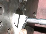 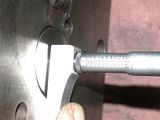 Sorry for the glare. Both sit deeper into the head than the range given in the book. Does that mean I need new valve seats? What happens if the valves sit too deep in the head? What is the outcome of that? Does it hurt or affect performance? |
|
rayh
CTW Member
 Devonn 554
Posts: 52
|
Post by rayh on Dec 12, 2009 23:10:15 GMT -5
Rob:
The valve sitting lower in the head will only reduce the compression slightly. It is safer to be deeper in the header than too high and clash with the piston.
|
|
rayh
CTW Member
 Devonn 554
Posts: 52
|
Post by rayh on Dec 12, 2009 23:17:14 GMT -5
Check the air intake system carefully for dirt. This is showing signs of premature failure from dust. The wear on the sleeves is far too much for 1000 hrs. I have seen 10k engines with less.
I have noticed strange patterns on 3 cylinders on the head. It appears to be caused by the piston coming very, very close or hitting the head. When you reassemble this engine, check how high the pistons are coming above the sleeves. There could be a problem.
|
|
rayh
CTW Member
 Devonn 554
Posts: 52
|
Post by rayh on Dec 12, 2009 23:18:00 GMT -5
Very good documentation job!!!!!
|
|
|
|
Post by bradblazer on Dec 13, 2009 0:54:20 GMT -5
Rob,
I am of course disappointed at the early wear on your engine but I am thrilled that you are taking the time as usual to fully document your impressive progress. I wish I could offer good advise but I have never overhauled an engine.
I was trying to figure out why you ars seeing so much wear and I like Ray's suggestion of a dusty environment which I know you've confirmed in the past. Maybe the OEM air filter quality wasn't too good? Hopefully my oil-bath filter is better. I also don't think I operate in as much dust as you have.
Could vibration also be a factor? I know mine isn't the smoothest running thing ever. Maybe it would be good to have it balanced while it is apart.
Sounds like Chip is providing excellent parts support for our orphans. What a great guy.
Keep up the good work - I'm sure you'll have H.K. back in action in record time.
Brad
|
|
GuglioLS
Administrator  Jinma354 LE
Posts: 1,276
|
Post by GuglioLS on Dec 13, 2009 1:09:31 GMT -5
Holly smokes Rob you didn't waist any time tearing your engine down to bits and pieces. Those two cylinders do look pretty worn out. Too bad in such a short period of time. I have to agree with rayh there seems to be allot of pre-mature wear. Perhaps make sure the intake system is air tight and that nothing is getting around the air filter. After your rebuild no doubt you might notice a "little" more power and a smother running engine. Glad to see you got some use out of that heat gun after all this time. So I guess it's getting pretty cold there? Our low so far this season was -18*f a couple of weeks ago. Not much snow but sure has been bitter cold.
I wouldn't sweat the "out of tolerance" depth on the valves. The loss of compression would be unsubstantial and un-noticeable. I suppose it would be prudent to check that you can still get the valve lash adjustment in spec though.
I look forward to seeing the completion of your re-build when all the parts come it. As always you tell an interesting story I cannot resist. I hope you can get Huge Kama back together soon.
Larry
|
|
PJ
CTW Expert

Posts: 176
|
Post by PJ on Dec 13, 2009 8:30:02 GMT -5
Rob, Great job of documenting your work! Due to the suggestions about your dry air filter and excessive wear in your cylinders, I'm going to change my dry filter on my Foton to an oil bath as soon as I can find one big enough. PJ
|
|
rayh
CTW Member
 Devonn 554
Posts: 52
|
Post by rayh on Dec 13, 2009 13:11:15 GMT -5
Don't be fooled thinking oil bath are better at removing dust. If all conditions are perfect, they work good, but if they are slightly neglected, trouble can come quick. They will not work good on slopes. They must be level.
Dry filters are much more suitable for general use, but you need a good filter. I have found the Chinese filters to be not the best. They will allow dirt to come through. Find a GOOD - USA filter replacement. (BALDWIN or NAPA or FRAM) They have better quality control. If you are still afraid of dirt coming in, find a filter arrangement with a saftey liner (2 elements). Don't go backwards to an OIL BATH system. We threw them away years ago.
|
|