|
|
Post by bradblazer on Dec 19, 2009 11:56:21 GMT -5
Yes - just mount the precleaner on the filter intake. Not sure how your intake is oriented but I think the precleaners are all designed to be mounted vertically.
|
|
FlyHiFlyLo
Administrator  2007 Jinma 554LE
Posts: 425
|
Post by FlyHiFlyLo on Dec 19, 2009 22:29:43 GMT -5
If all you valves are within .005 like you mentioned you will be fine. You can install one spring, retainer and lock. Measure the installed height. Then just take the springs to any machine shop and just have them test them that they are all close in pressure at that height. I don't trust the heat treat on our Chinese stuff.
Or just go for it!
|
|
3RRL
Administrator  Huge Kama
Posts: 2,027 
|
Post by 3RRL on Dec 19, 2009 23:28:36 GMT -5
If all you valves are within .005 like you mentioned you will be fine. You can install one spring, retainer and lock. Measure the installed height. Then just take the springs to any machine shop and just have them test them that they are all close in pressure at that height. I don't trust the heat treat on our Chinese stuff. Or just go for it! Ha... I just went for it as you can see from the batch of photos. I did, however, depth mic each one after lapping and also with the valve springs locked on. I performed the leak test early this morning. The 2 new valves passed the test 100%. The test is to pour kerosene (I used diesel) into the intake and exhaust ports .. fill them up and watch the valves for leaks. The valves should not leak for a minimum of 3 minutes. I tried to take some photos to show the fluid in the ports along with the valves. There was no leakage or seepage at all on the new valves so they passed with flying colors! First photo is the new intake valve and second one is the exhaust valve. 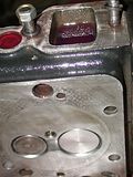 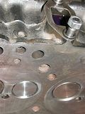 Sorry to say only one of the old valves passed the test (barely 2 min 45 seconds). The others leaked within 45 seconds. I decided to use the rest of the new valves including replacing the marginal one. That meant starting over taking all the valve springs off again, and of course all that meticulous cleaning to do after lapping and bluing every one of them off, let alone the extra leak tests. Anyway, I figure I had a better chance of lapping them in correctly than chasing the old valves. Plus the all the new valves seated within that depth tolerance better. After I got the all the new valves completed and installed, I re-checked them with the leak test. Guess what, 2 intake valves still did not make the 3 minutes. I had to remove them ( a couple times) until I got all of them to pass the 3 minute no leak test. I'm glad I did and I'm proud of myself for taking the extra time to change them out even though I was tempted to say ... "ok, that's good enough". Especially after re-lapping and bluing those intake valves several times until they sealed 100%. Now I KNOW for certain they are all leak proof. But I also smell like a diesel fuel truck.  Photos below show leak if you look close, and second one of all the new valves installed.  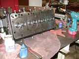 |
|
|
|
Post by tuffytractor on Dec 20, 2009 14:35:41 GMT -5
Rob,
Fairly impressive, the way you jumped in to take this on. Sad to here that it was so early on in the life of Huge Kama. Really appreciate the documentation, plus all the input you are receiving that allows you to make the best of the situation. Great work, as always.
|
|
|
|
Post by stumppuller on Dec 20, 2009 21:30:57 GMT -5
Rob,
I, too, am always impressed with your willingness to jump right into a mess & figure out solutions to the problems. As a side note, I have a manual valve grinding gizmo which is some sort of gearbox inside a stamped metal housing with a crank on the outside & a suction cup drive for the valve. When you turn the hand crank the cup revolves say 220 degrees CW, & then reverses direction for say 60 degrees. It keeps this "2 steps forward, one step back" for as long as you turn the crank. The idea is that this motion works the grinding paste back and forth eliminating tracking/grooving which could occurr if you just power it in one direction.
The other thing that I remember from my motorcycle engine rebuilding (Norton) is that the valve seat and valve land are ground to a 1/2 degree difference so that you essentially create a line contact. That "line" is then lapped into seating, creating a contact slightly thicker than a circular line. What I was told/read was that a matched angle on the valve & seat would not seal effectively as the area is too large. the "line" seating created a higher unit-area force and thus sealed better. This was all gas engine stuff and diesels may be different.
Just some thoughts.
Bruce
|
|
3RRL
Administrator  Huge Kama
Posts: 2,027 
|
Post by 3RRL on Dec 20, 2009 22:31:33 GMT -5
Thanks guys,
For lapping I used those wooden handled suction cups bought at Harbor Freight.
I cut the handle in half and turned it down to fit a 3/8" drill chuck. Then I used my Makita going forward for several revolutions and then backwards. I did that over and over again. I also would back off a bit and slowly press in so the valve turned truly concentric with the valve guides. I could see if you put a lot of pressure on, the valve could follow the seat (if they were not concentric). So going in and out sort of lapped away the "hi spots". I could not spin the lap very fast either, because if not dead on center, it would slide off the valve head.
Anyway, I managed to get it right after several tries.
Now I can move on to checking the connecting rod bearings and crankshaft journals for roundness and proper clearance. I will also start preparing the new sleeve liners for installation. I took this next week off so I'll have a little extra time to finish fencing Loretta's garden (shit ... again ;D) and also work on Huge Kama.
Rob-
|
|
3RRL
Administrator  Huge Kama
Posts: 2,027 
|
Post by 3RRL on Dec 20, 2009 22:56:10 GMT -5
I was pretty excited about the valve job coming out so good. Next was to check the crankshaft journals and connecting rod bearings for roundness and proper clearance. It took me a little while attaching them and taking them off again, but it was worth doing to be sure they were not shot. I got some red and green Plasti-gage. The green is .025-.076mm(.001"-.003" and the red is .051 to .152mm(.002"-.006"). I also installed the new journal bearings onto the connecting rod. Shown are old ones out and new ones in.  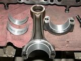 |
|
3RRL
Administrator  Huge Kama
Posts: 2,027 
|
Post by 3RRL on Dec 20, 2009 23:30:37 GMT -5
Regarding the journal bearings... The photo of my manual shows the clearance needs to be between .04~.098mm(.0015"~.0038").  I used the green hoping to fall within the acceptable clearance written in my manual. I put a length of Plasti-gage diagonal (with a dab of grease to hold it) on top of the journal and inside the connecting rod cap. To read the plasti-gage scale, you compare the squished width (after tightening) to the scale on the paper package. Whatever width matches up is the amount of clearance you have. I had to crawl underneath and tighten the bearing cap while Loretta held the connecting rod in place.   After removing the connecting rod from the crankshaft, I could see the Plasti-gage on top of the journal had squished down a little wider than the .001" mark on the scale, but I think it moved a little upon removal. So I think it's abut as wide as the .001" mark. The bottom side was right at the .001" width but no pic of that because it was too hard to get a photo upside down. 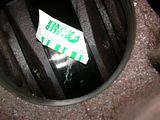 So I figure I have a total of .002" clearance or less in those journal bearings. Looks like I'm right in the middle of the clearance tolerance. Next on the agenda is to prepare the new sleeve liners for installation into the engine block. Rob- |
|
3RRL
Administrator  Huge Kama
Posts: 2,027 
|
Post by 3RRL on Dec 21, 2009 20:41:41 GMT -5
Today I focused on installing the new sleeve liners. Before doing so I wanted to be sure that the bore in the engine had a nice lead in so the "O" rings would slide over without shearing. When I removed the old sleeves, I saw several had sheared so I wanted to avoid doing the same thing. I took a little dremel flapper wheel and ground a 45 degree lead in on it. I went into the bores and smoothed out the rough sharp edges. Then took some 320 wet and dry and hand worked it. Sorry, the bottom of the bore didn't come out so good in this photo below. 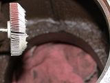 After that I started to measure the counter bores to see if they were all the same. I also mic'ed the head thickness on each sleeve. Then I measured the step above the head. What I was trying to do was make sure all the steps would sit the same distance above the engine block. I don't know how good the head gasket will seal if they are different heights so I thought it was a good thing to do...maybe it was unnecessary?, but when I build molds that have counter bores and inserts with heads like that, I grind them all alike or one will keep the others from shutting off. 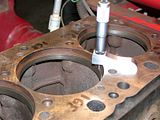   |
|
3RRL
Administrator  Huge Kama
Posts: 2,027 
|
Post by 3RRL on Dec 21, 2009 21:01:50 GMT -5
What I found was interesting. One of the counter bores in the engine was .009" shallower than the other three. Well, that cant' be good? The head thickness on the sleeves were all identical so that was good. But on one of them, the little step was .003" taller than the rest. What I wanted to do was to reduce the head thickness by .009" on the one sleeve to fit that shallow counter bore. That way, the top of the sleeve would end up the same height as the others. Then reduce the little step to be equal in height as the others. I figured there was nothing in the bottom holding the sleeve from dropping into the crankcase, so the heads are what keep the sleeves from sinking deeper. But when I set up the on sleeve in my lathe, I couldn't get both the diameter and the face (of the head) to come in to zero. So I decided that the diameter was more important, since that's what fits the bores in the block. I indicated it in to zero and machined the head concentric and parallel to diameter. That meant kissing the underside of the head first, then cutting the top of it to establish the new head thickness. You can see the dykem (red) that was partially machined when I took a kiss pass on it. Then I machined it to the new head thickness.  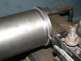   |
|
3RRL
Administrator  Huge Kama
Posts: 2,027 
|
Post by 3RRL on Dec 21, 2009 21:20:48 GMT -5
When I finished checking size, I added some chamfers before unchucking it. Took it over to the surface plate to check the little step and it was right on the money.  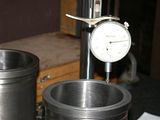 So now all the sleeves will (should) protrude above the engine the same amount...and they did. The head gasket will have a better chance to seal properly and evenly. When I put the sleeves into the bores, the "O" rings went past the top part easily, but they were pretty tight going into the bottom part where they seal off. I had polished that lead in and also greased the "O" rings so they would "slide" past that point. I can see how the original ones got sheared. Instead of pounding the soft cast sleeves in, I actually took the head itself and placed it gently on top of them all. I used the head bolts to seat the sleeves by evenly tightening them until the sleeve heads hit the counter bores. There was no way I was gonna take the engine block and machine that one counter bore deeper! I presume they all should have been the same depth, right? BTW, what do you guys do with the head gasket? Do you put a gasket sealer on both sides of the gasket? Or is it not necessary? I was going to add a gasket sealer on both sides of it.   |
|
3RRL
Administrator  Huge Kama
Posts: 2,027 
|
Post by 3RRL on Dec 21, 2009 21:36:59 GMT -5
Before I stopped for the day, I fit the rings into the new sleeves. I wanted to check the ring gap to be sure it was within tolerance. I measured the gap with a feeler gage. An .011" went in and a .012" did not. The tolerance for the top ring is 0.30mm~0.45mm which is .0118" ~ .0177", so the top rings were at the low end of the clearance. The other rings were toleranced 0.25~0.40mm which is .0098"~ .0157". The .011" feeler gage went in those as well. After checking, I then installed the rings onto the pistons. They are ready to go back into the engine tomorrow. The new piston is on it's connecting rod. I had to heat the piston up to slide the wrist pin in. And all of the connecting rods have new journal bearing in them now. I'd still like to know about using gasket sealer on the head gasket, or not.  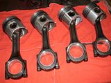 |
|
3RRL
Administrator  Huge Kama
Posts: 2,027 
|
Post by 3RRL on Dec 23, 2009 11:40:16 GMT -5
Hi guys, Well, below is a better photo of the new gasket and it did feel slick. But too late, it's already on and I used a thin film of sealer. I don't think it should hurt.  So like I said above, I did get some progress done. I got one of those ring closing things to install the rings and pistons into the engine block. They rings were pretty springy so I'm glad I got it. I slid the pistons in using that apparatus. BTW, I learned it was better to turn the crank so the journal was up when inserting the pistons. I insert one piston with the crank journal down and the bearing on the connecting rod fell off. 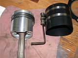  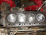 |
|
3RRL
Administrator  Huge Kama
Posts: 2,027 
|
Post by 3RRL on Dec 23, 2009 12:07:50 GMT -5
I have an S&K 1/2" drive 250ft/lb torque wrench. It's a fairly decent wrench where you can dial the desired torque. It has both N/m and ft/lb scales on it. 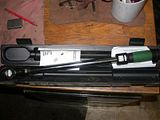 I went underneath to put on the bearing caps and torque in 3 steps to spec. I put the oil pan back on which has a re-usable rubber gasket. It was in good shape. Then I re-installed the front drive shaft. So now the entire bottom end is done and buttoned up. After that I put the head on, and the rocker arm assembly. I torqued the head to spec in steps using a small amount of oil on the bolts as stated in the Manual. But I just snugged/tightened the rocker arm assembly.    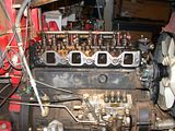 I'm not sure if there is a torque value for the rocker arm assembly? Somewhere I had written down like 65/70ft/lbs, but I couldn't find a torque spec in the manual for that. Right now they are just snugged up. Does anyone know the torque value for that? Anyway, I'm making progress slowly. I still have a lot of cleaning and other re-assembly to do today, so I will check the forum this afternoon before I set the valve lash. Please let me know that torque value... |
|
quikduk
CTW Life Member
   Dog House
Posts: 552
|
Post by quikduk on Dec 23, 2009 12:33:32 GMT -5
Well this explains why you didn't answer your phone... ;D It looks like you are almost there...and boy am I glad it wasn't me having to do this ATM. I was thinking the only other PITA you could have had was to do this in the mud and tents at South Camp...  BTW, what type of assembly lube did you use on the bearing journals. pistons etc...or was it just engine oil? Also, are you planning on performing a compression test when you are finished just to see what the new components have given you (besides no leaks or blowby)? Great job Rob (& Loretta)!!!  |
|