3RRL
Administrator  Huge Kama
Posts: 2,027 
|
Post by 3RRL on Nov 12, 2010 14:07:13 GMT -5
Hello fellow members. Boy, it's been a long time since I wrote a new thread. But I recently acquired a new (used) LW-8 Backhoe from my good friend Scott. It has quite a bit more reach than my Italian made Nardi 220 hoe, so I was very interested in getting it. It also weighs a lot more and has a little more power, which made it even more important to make a super deluxe subframe for the new hoe. Everyone knows how important it is to have a really good subframe to protect the tractor from stress. Below is a photo of the LW-8 hoe attached to my 55hp Kama. You can see I have it attached by the 3 point lower drag links and the top link. Even with the stabilizers down on the ground, it moved around quite a bit. I decided to get it into the barn and start figuring out how to make the subframe for it. Rob- 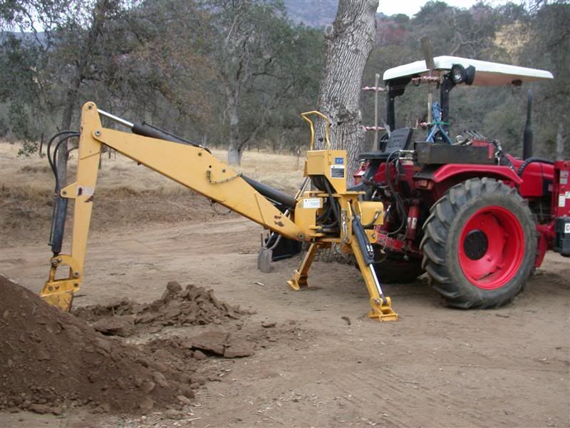 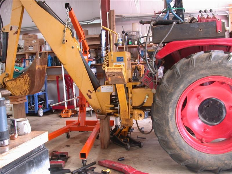 |
|
3RRL
Administrator  Huge Kama
Posts: 2,027 
|
Post by 3RRL on Nov 12, 2010 14:17:08 GMT -5
What I decided to do was to make a Diamond shaped subframe. You can see from the (poor) drawing that the new subframe would be super rigid with little or zero flex once it was done. It connects the backhoe subframe parts (welded to the backhoe) to the front loader braces and also to the ROPS, which is rigidly connected to the top of the rear end of the tractor. The front loader support is also rigidly connected underneath the rear end. The ROPS acts as the center of the Diamond shape, transferring all the stress to the loader frame braces, which in turn supports the engine, bell housing, transfer case, transmission and rear end. Everything will be all tied in together via the frames. In addition on the backhoe frame parts, there will be cross tubes which connect the lower and upper supports, as well as cross tubes running from one side to the other. I figure this would give me maximum rigidity not only up and down, but also for the torsional sideways stress loads. Below is the concept I used. 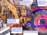 And it must be easy to put on and take off. The plan is to have attachment points on the tractor where I can back the tractor up to the hoe and put on the PTO hydraulic pump. Then drive in more until the bottom supports slide into the mating tractor bottom supports. I will then pin it to the bottom frame (on the tractor) when the hoe is tilted down with the bottom supports level. Then, using the boom and stabilizers, rotate the hoe upwards until I can bolt the top connection onto the ROPS using 3/4"-10 grade 8 bolts. The 1" diameter bottom pins are the pivot point to allow the hoe to rotate upwards once pinned down there. Rob- |
|
|
|
Post by Ronmar on Nov 12, 2010 19:44:19 GMT -5
I like the diamond frame. Triangles are our friends:) Will the forward running strut between ROPS and loader frame be in the way when mounting/dismounting the tractor, or interfere with pedal operations? I don't know if I would have enough room to do something like that on my 284. It will shorten the moment arm on the rops, possibly increasing it's strength, if god forbid you ever need to use it for it's intended purpose...
|
|
3RRL
Administrator  Huge Kama
Posts: 2,027 
|
Post by 3RRL on Nov 12, 2010 21:10:01 GMT -5
I like the diamond frame. Triangles are our friends:) Will the forward running strut between ROPS and loader frame be in the way when mounting/dismounting the tractor, or interfere with pedal operations? I don't know if I would have enough room to do something like that on my 284. It will shorten the moment arm on the rops, possibly increasing it's strength, if god forbid you ever need to use it for it's intended purpose... Hi Ron, The way I mounted the forward running strut was right against the fender(s). They just clear the accelerator pedal on the right and don't come close to the clutch or brake pedals. It clears the top of the floor board too, so they are a little in the way of getting in and out, but not bad at all. I made and extra set of mounting steps to deal with that problem. I agree the ROPS is now strengthened, at least from the triangle down to the rear end. Coming up are photos of where those struts sit. Rob- |
|
3RRL
Administrator  Huge Kama
Posts: 2,027 
|
Post by 3RRL on Nov 12, 2010 22:19:31 GMT -5
To continue, below are photos of the front struts I made. They are bolted via plates to the FEL tubes in front, and welded to the ROPS inside the cab. That way If I ever have to take the loader off, I can unscrew the bolts and leave the struts connected to the ROPS. (I know I'm going to get heck from the ROPS police, but that's what I did.) I've had that rear bracket with the bolt hole in it on there for 4 years now. I used that one for the previous Nardi backhoe subframe connection. But that one was pinned together there and also on the backhoe, which left room for movement. The LW-8 subframe will be bolted up there with 3/4"-10 grade 8 bolts. Rob- 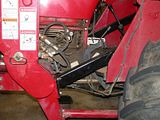 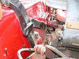 |
|
3RRL
Administrator  Huge Kama
Posts: 2,027 
|
Post by 3RRL on Nov 12, 2010 22:21:19 GMT -5
In the previous photo, and the second one below, you can see how the Koyker FEL frame has 1/2" thick braces going forward to the motor, and a 2" diameter tube going back to the rear end to take the stress off the motor and transmission and all the bolts holding the tractor together. With that new strut, the loader frame is now supported above and below the rear end making it super sturdy. The ROPS forms the third leg of the triangle for those connections. The front struts run against the inside of the fenders and miss the accelerator, brake and clutch pedals. I now have to step over them when entering the cab, so I made and extra set of steps to get in and out of the tractor. Also made 2 sets of steps to get in and out of the backhoe. Rob- 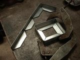 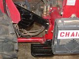 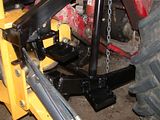 |
|
|
|
Post by Ronmar on Nov 12, 2010 22:26:55 GMT -5
That is Beautiful!
|
|
3RRL
Administrator  Huge Kama
Posts: 2,027 
|
Post by 3RRL on Nov 12, 2010 22:34:09 GMT -5
Next was to make the lower backhoe subframe struts. These would be welded onto the bottom of the backhoe frame. The other end is where they are pinned onto the tractor receiving support frame. I used heavy wall 2" x 4" tubing for the lower frame and 2" x 3" for the upper frame (and those front struts as well). The photos below show the receiving support bars where the backhoe will be connected with 1" diameter pins. They are welded onto the FEL rear support tube plate, and also re-inforced with gussets so they won't budge. 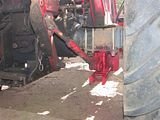 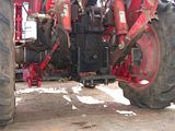 |
|
3RRL
Administrator  Huge Kama
Posts: 2,027 
|
Post by 3RRL on Nov 12, 2010 23:09:40 GMT -5
Hey Ron, thanks man! Glad you like it so far.  Now that I have the lower receivers reinforced, and the front support tubes installed, I got to making the upper backhoe subframe. They are shown in the first photo below. BTW, all the holes are bored through the thick wall rectangular tubing and then have either DOM tubing (drawn over mandrel) welded in for the holes, or solid steel inserted for reinforcement. The lower receivers on the tractor have solid steel on the inside of the rectangular tubing and the mating ones on the backhoe have DOM. An example of the steel inserted is shown when making the bolt on end of the upper backhoe frames shown in the 2nd photo below. Solid #2 steel (4130) is welded into the rectangular tubing. The lower backhoe support frame (last photo below) are welded to the bottom of the backhoe. The other end is connected to the receiving supports on the tractor via those 1" diameter pins. Those are the only place where this subframe is pinned. 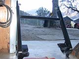 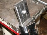 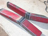 |
|
3RRL
Administrator  Huge Kama
Posts: 2,027 
|
Post by 3RRL on Nov 12, 2010 23:17:19 GMT -5
OK, that's all there is to it. Below are photos of the backhoe subframe completed. I had to fixture up every connection before and during all the welding to keep a perfect alignment. I had to add some rectangular tubing and plates to both the upper and lower backhoe connections to make them support the hoe properly. Other than that, it came out pretty sweet. 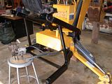 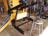 Note also that both upper and lower frames are cross connected vertically and horizontally to each other with 1-1/2" diameter round tubing. This pretty much keeps the whole shebang square under load. When connected up to the tractor, the diamond shape is completed and further bracing throughout the tractor and backhoe is achieved...front to rear. |
|
3RRL
Administrator  Huge Kama
Posts: 2,027 
|
Post by 3RRL on Nov 12, 2010 23:31:59 GMT -5
So here is how the backhoe is connected up to the tractor. The first photo below shows the upper connection bolted together. It also shows the front strut support going down to the front FEL support. The second photo shows the lower connection pinned together. I took it outside for a tryout after that. 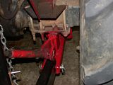 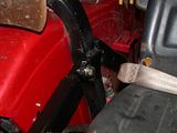 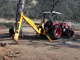 You can't believe how worried I was about line up before I connected it up. I was very pleased when I backed the tractor up to the backhoe and the lower connections lined up to be pinned together easily. Then I used the backhoe to push itself up, rotating up on the lower connecting pins until the upper bars touched the ROPS (it cannot rotate up any further). I then screwed in the 3/4"-10 bolts and the subframe was 100% connected. Rob- |
|
3RRL
Administrator  Huge Kama
Posts: 2,027 
|
Post by 3RRL on Nov 12, 2010 23:44:53 GMT -5
I wanted to share a couple more things. Before I put the backhoe back together, I machined out the plate covering the valve. There were "+" shaped clearance slots for the control handles in it, making it impossible to control the backhoe with simultaneous movements such as pulling in the dipper stick and curling the bucket at the same time. Or extending the boom and swinging at the same time. Boring out that plate made it act like a regular backhoe. And of course, my dear wife Loretta helped me through the whole project and did all the paint touch up for me, as usual. 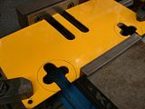 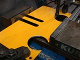 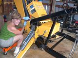 |
|
3RRL
Administrator  Huge Kama
Posts: 2,027 
|
Post by 3RRL on Nov 12, 2010 23:57:00 GMT -5
There were a couple last things to do before it was ready to dig. First, I had to secure the PTO pump to keep it from spinning (first photo). Second, because I do not use the lower links, I had to make sure they didn't creep down onto the hydraulic tank which is mounted on the backhoe. I made a bar which holds the lower links in position ... not only up, but spread the right distance apart so they will clear properly when backing the tractor up to the backhoe. I put this on before I connect the PTO pump, and then back in the rest of the way for the hook up. 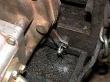 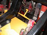 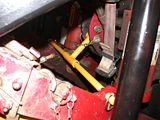 After that, I took the tractor out and started to dig a 60' long trench for the water and electrical lines for Loretta's garden shed. That's one of the projects we will be working on in the next few months. Perfect timing...  Rob- 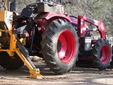 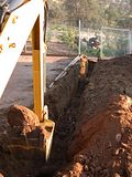 |
|
|
|
Post by Rich Waugh on Nov 13, 2010 1:47:32 GMT -5
As usual, your meticulous planning and execution have resulted in a really excellent job, Rob. After all the others, this no longer surprises me - you'd have to really screw something up horribly to surprise me. ;D
Seeing that is almost enough to make me want a backhoe, but I just can't justify it - yet. When/if I ever get to digging the cistern and foundation of the house I hope to get built before I get too much older, I'll probably cave in and get one.
Does that 'hoe have the original Jinma control valve(s)? It seems to do the compound moves that others I've seen said it wouldn't do. Perhaps they never thought of opening up the stick travel like you did?
Another great job!
Rich
|
|
3RRL
Administrator  Huge Kama
Posts: 2,027 
|
Post by 3RRL on Nov 13, 2010 9:46:50 GMT -5
As usual, your meticulous planning and execution have resulted in a really excellent job, Rob. After all the others, this no longer surprises me - you'd have to really screw something up horribly to surprise me. ;D Seeing that is almost enough to make me want a backhoe, but I just can't justify it - yet. When/if I ever get to digging the cistern and foundation of the house I hope to get built before I get too much older, I'll probably cave in and get one. Does that 'hoe have the original Jinma control valve(s)? It seems to do the compound moves that others I've seen said it wouldn't do. Perhaps they never thought of opening up the stick travel like you did? Another great job! Rich Hi Rich, thanks for checking out this thread. This hoe has the original valve on it and it does function correctly (true 3rd function) if the control handle plate is modified like I did. However, I did not come up with the idea. I believe Tim Wales, long time member here, was the first (if I remember correctly) to do that to his backhoe plate. Having said that, and having owned the Nardi backhoe for almost 5 years knowing it should do that, I think I would've attempted it anyway. The valve, however, is not nearly the quality and smoothness of the Nardi. I don't know if you noticed or not, but the photos show the huge Kama fronts and rears off the ground in one of the last pictures. This subframe is so rock solid that even the slightest movement of the backhoe is absorbed by the subframe. In other words, there is Zero play in it. And I mean absolutely ZERO play! And once the backhoe is up on it's stabilizer feet, it feels rock solid when digging. When I push one of the stabilizers down, or the boom down, the entire tractor moves with it. My other subframe for the Nardi backhoe always allowed the backhoe to move independently of the the tractor for a few inches before that subframe tightened up. That shows (to me) how rigid this new subframe turned out. It not only solidifies the backhoe subframe, but has solidified the FEL subframe as well (through the front struts connection). So it was a worthwhile investment for me in more than one way. I'm very confident that there will be no damage to my tractor either from backhoe or FEL use now. Rob- |
|