3RRL
Administrator  Huge Kama
Posts: 2,027 
|
Post by 3RRL on Mar 3, 2008 22:56:50 GMT -5
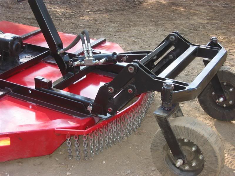
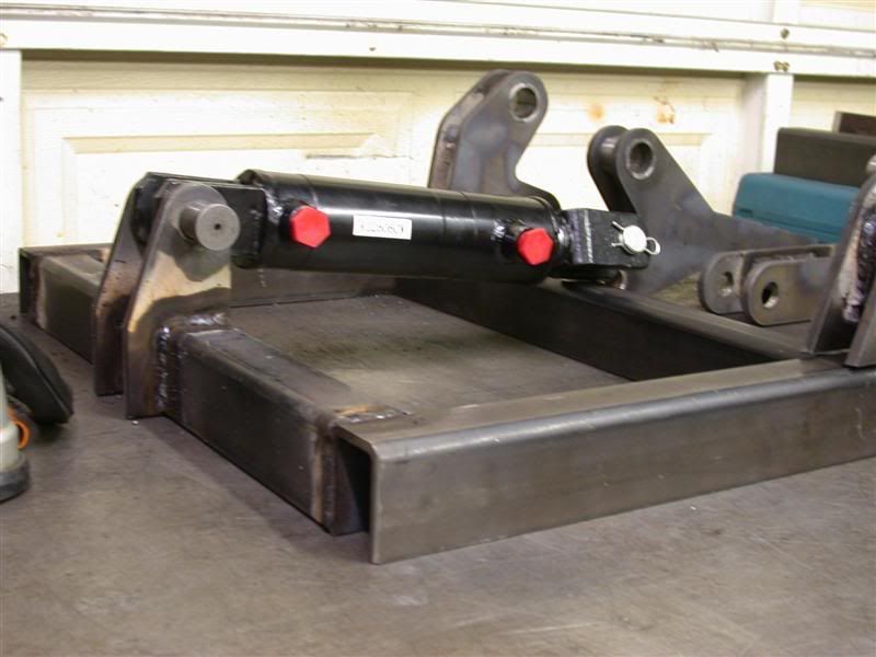
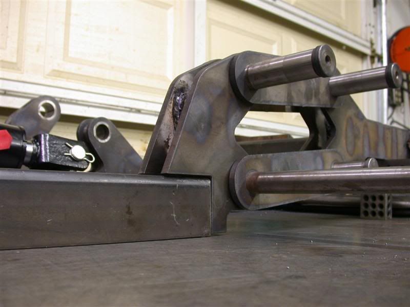
This is part of the frame that will be welded to the rear of the RC. I got a 3" cylinder with a 1-1/2" diameter rod for extra strength. 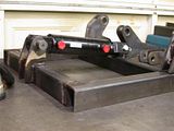 I am not going to weld up the front of the cylinder mount until I bring it up to the property. I need to mount the frame onto the RC and then position the front cylinder mount to give me the wheel travel I want. I'll have to check it there to see, by moving the cylinder in and out. Then I'll weld that part last. Here are the links all pinned together. I still have to cut off the hardened pins to length and drill them for grease fittings. If I remember right, they are case hardened so I can tap the holes after getting through the hardened surface. (I hope). There is also a close up of the linkage. I have not cleaned up my welds yet because I wanted to post some progress before leaving for camp. 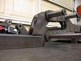 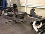 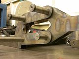 Rob- |
|
3RRL
Administrator
Huge Kama
Posts: 2,027
|
Post by 3RRL on Mar 3, 2008 22:59:56 GMT -5
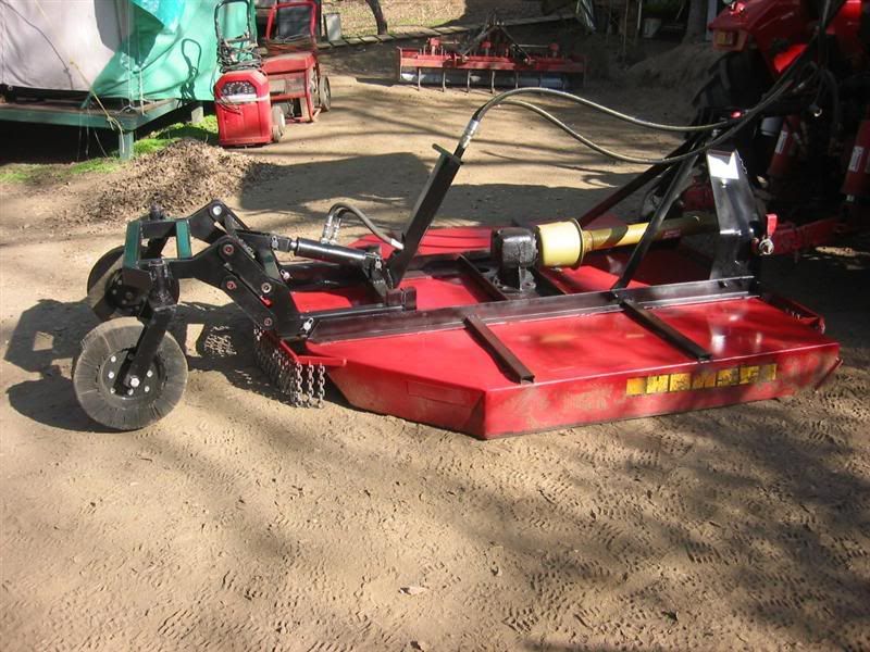
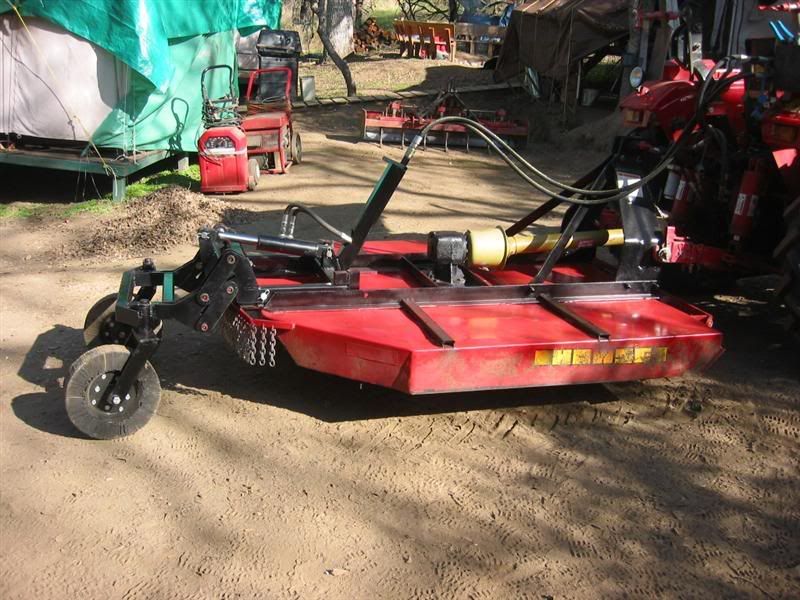
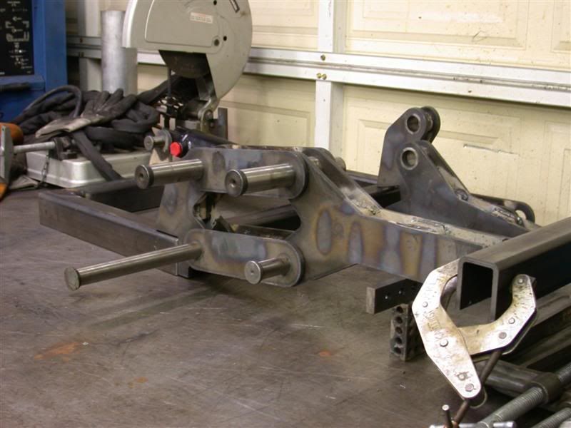
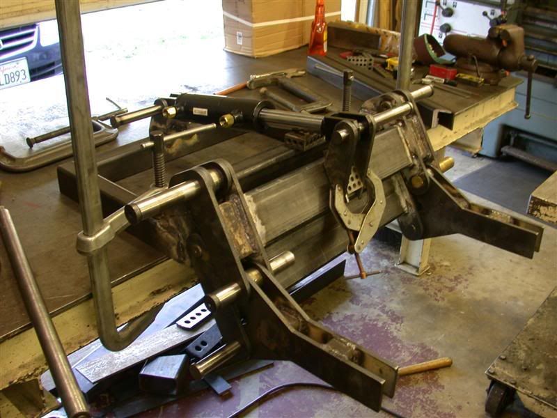
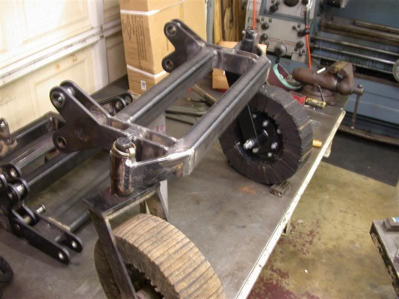
I got the rest of the leveling frame welded together and the hydraulic mounts too. I had to clamp it all together for welding and keep all the pivot mounts in line. Here is the set up, partially welded. I made the wheel bushing for the new (2nd) wheel and those brackets to mount to the trailing end. Here are a couple photos with both wheels in. The dual trailing wheels sit 34" apart. 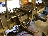 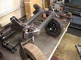 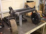 I used the old wheel bearing and cut the frame to fit my new frame and then made the new side to match. I've still got a lot of weld grinding and cleaning to do before it's ready for primer and final coat of red paint. I will most likely put it all together up at camp. |
|
3RRL
Administrator
Huge Kama
Posts: 2,027
|
Post by 3RRL on Mar 3, 2008 23:02:16 GMT -5
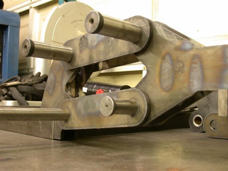
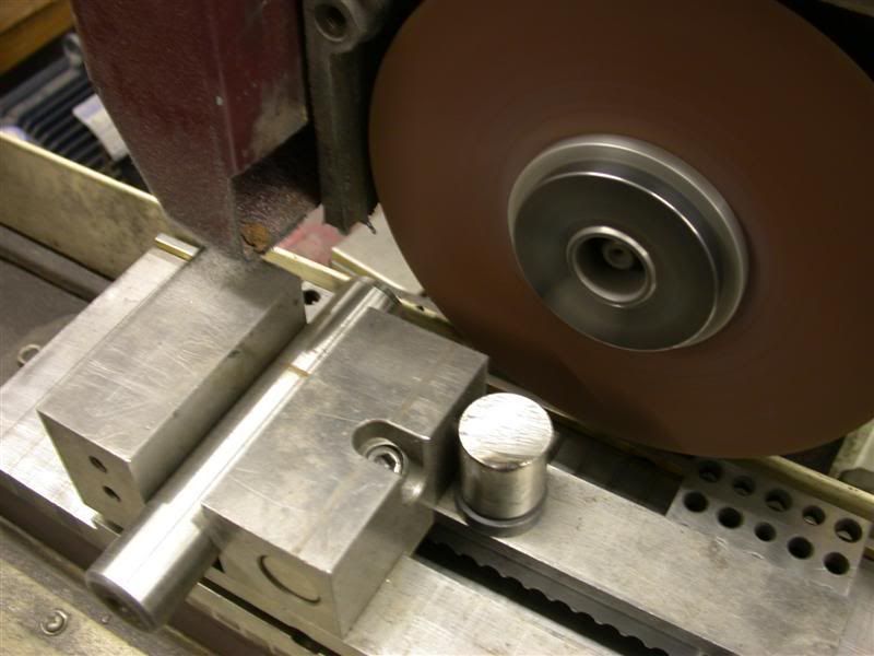
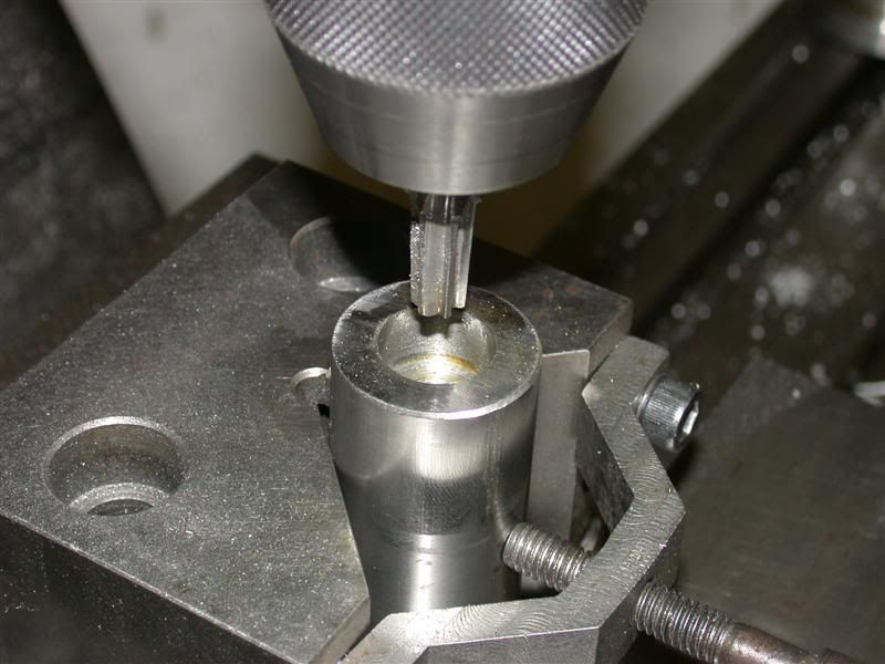
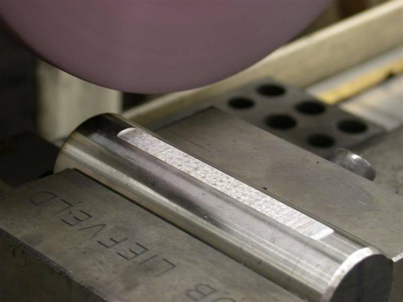
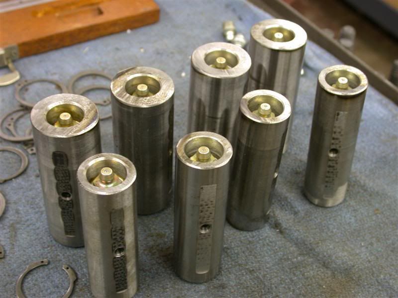
Since I am using hardened leader pins and bushings for the pivots, I had to make sure they could be greased properly due to the close fit between them. I didn't want them to rust shut. With a little warpage from all that welding, they tightened up somewhat too. But that is a good thing considering the linkage is like a giant chain link and I really wanted it as tight as possible. I don't think the 2-1/2" diameter hydraulic cylinder will care how tight it is. Surprisingly, making those pins and bushings turned out harder than I thought because they were 60RC on the outside and 38Rc on the inside. I had to cut the pins off using my surface grinder with an 8" abrasive wheel that is 1/32" (.032") thick. It sliced the 1-1/4" diameter hardened leader pins like butter. I made 4 pins out of 1-1/4" diameter and 4 out of 1" diameter. Next was to drill the grease hole from one end and then open up to 11/32" and run in a 1/8 pipe tap reamer to help against snapping a tap off in there. Then tap. 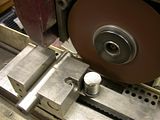 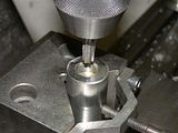 The next photos show that I had to grind 2 flats on the pins so the grease would flow end to end. Then had to drill side holes from each flat to the middle hole. I had to grind through the case hardened surface so I could use high speed drills to drill the inner steel which is only about 38RC hardness. Still hard to drill but I took my time and used cutting oil. I sharpened my drill bit with way more angle than the normal 118 degrees (like 140°) and less relief. I drilled half the length for the main hole and then from each flat to connect the path. So here they are with the Zerk fittings installed. I recessed them so they can't be broken off. Cool huh? 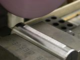 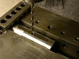 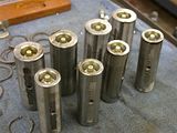 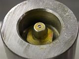 |
|
3RRL
Administrator
Huge Kama
Posts: 2,027
|
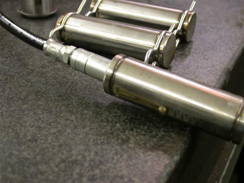
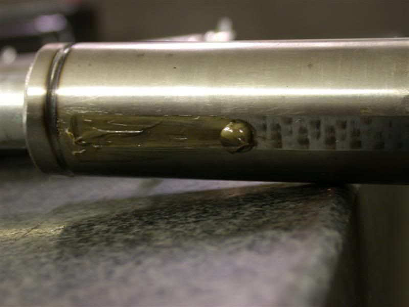
Post by 3RRL on Mar 3, 2008 23:06:39 GMT -5
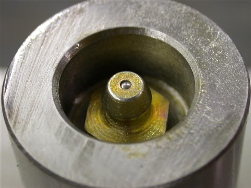
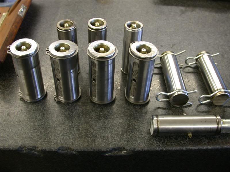
Finally, I got to grind the retainer ring slots on the ends. These pins will use circlip retainer rings to hold the pins in. I put on a 1/16" wide cut off wheel and plunged down the depth of the groove and rotated the pin in my whirly gig. Took it all in one pass. So here they are with the clips on. I decided not to lubricate the hydraulic cylinder pins. If you look closely, you can see grease coming out each side hole. and on this last photo, I pushed a bushing over the pin to show how the flat would work, distributing the grease over the length of the pin so the entire inner surface of the bushing gets coated when it rotates. 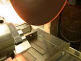 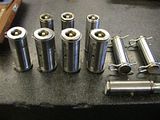 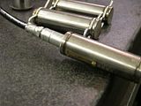 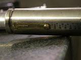 Still got to cut more of those 2" square tubes in half (length ways) to make the body more rigid on the rotary cutter itself, but I'll get to that later. That takes like forever to do one slit. I also need to assemble the DPOCV hard line to the hydraulic cylinder too. So there is still work left before I can get it to camp. Once I get up there and weld the supports and this wheel assembly onto the rotary cutter, I will have to scrounge for hydraulic hoses, fittings and QD's. And also make the brackets and install hose clamps for the lines. I am keeping to my original plans of using as much spare/ scrap stuff I have lying around to keep this a super low budget mod. That's why all this extra machining and stuff. Lot's of work left, but I can see the light at the end of the tunnel ... and it ain't no train. ;D Rob- |
|
3RRL
Administrator
Huge Kama
Posts: 2,027
|
Post by 3RRL on Mar 3, 2008 23:12:28 GMT -5
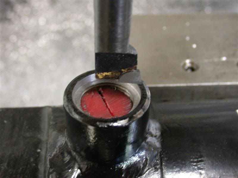
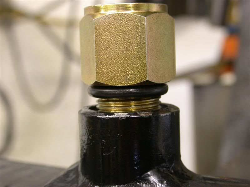
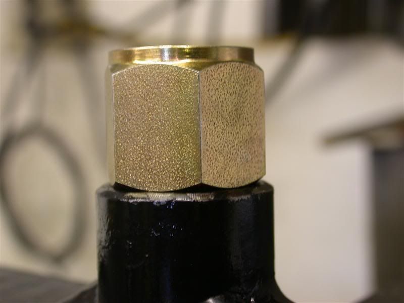
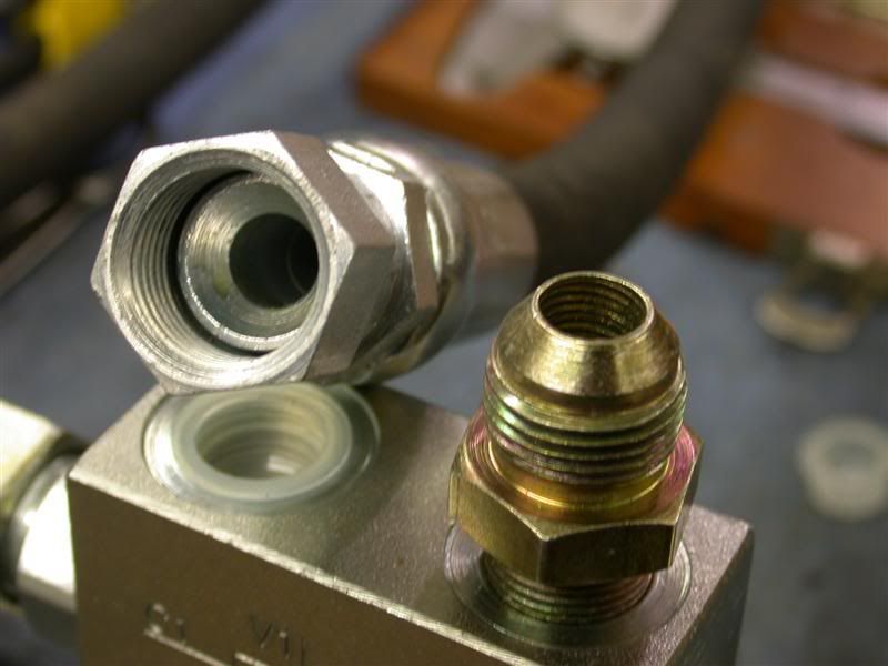
I managed to mount the double pilot operated check valve (DPOCV) which I bought from Mark over at CCM. Like you saw on my backhoe leg's mounting, those have Metric fittings and steel tubes. The hydraulic cylinder I bought is a 2-1/2" bore by 6" stroke, and it has a 1-1/2" rod. I chose it for the rod diameter for strength, since a small cylinder would work the rise and fall of the linkage. But I didn't want to bend the rod by hitting rocks or the severe bumps I go over. Since it eventually takes all the rear load/weight of the cutter and the new frame and linkage, it had to be beefy. Well, it had #8 SAE ports. The banjo bolts for the DPOCV are British 3/8" BSPP (parallel thread) so I had to find an adapter. Of course I could not find one, but did find a male JIC #8 to female BSPP, but no "O" ring to seal it. So I lathed off the JIC taper and then bored out the cylinder ports themselves to fit an "O" ring, which I put on the neck of the JIC fitting (now an SAE fitting  ). The red thing in the port is a plastic threaded plug to keep chips out. I fit it so it was in there perfect and tightened the fitting until the shoulder hit the port.  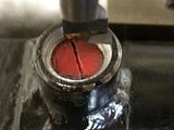 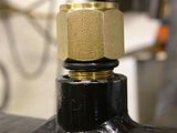 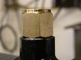 |
|
3RRL
Administrator
Huge Kama
Posts: 2,027
|
Post by 3RRL on Mar 3, 2008 23:15:44 GMT -5
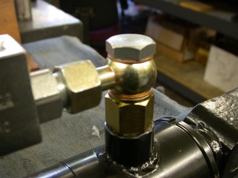
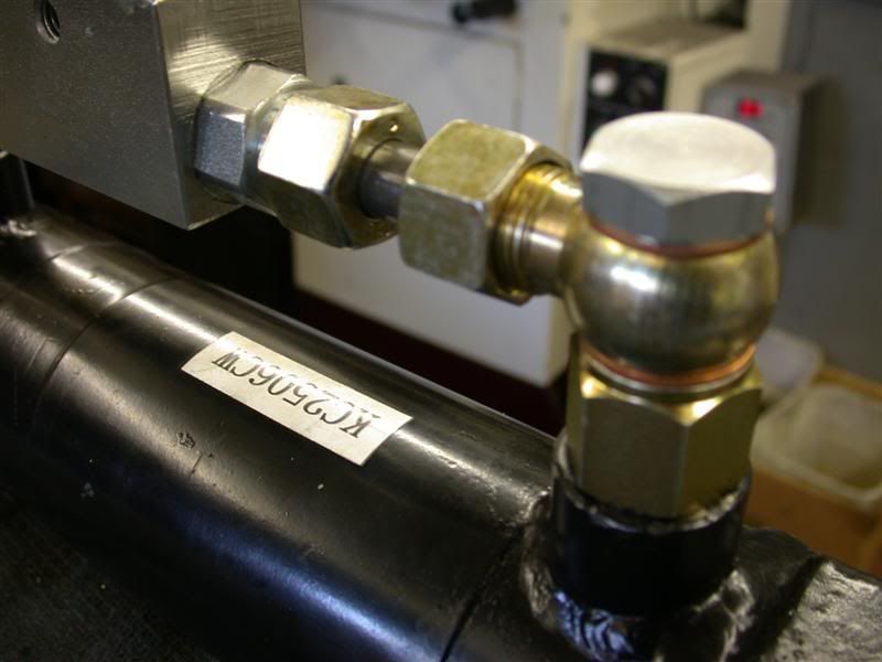
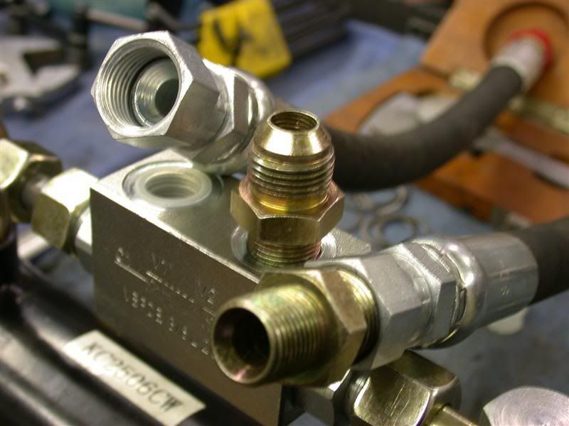
Then I cut the 12mm steel tube to length and installed the DPOCV onto the cylinder. Here are a couple shots of the fittings and check valve installed. They show the banjo fittings and copper washers and adapters. It came out super clean so I am happy with that part. 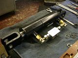 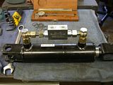 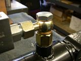 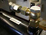 Now, the in and out ports of the DPOCV are also 3/8 British, but BSPT (taper thread). So had to get an adapter for that too, to fit my short hydraulic hoses which have JIC #8 ends. These were scrap hoses from another project and had the JIC ends put on. I could've had them put BSP ends on, but opted for the cleaner install of the JIC fittings, in case I ever needed to dis-assemble the unit. Here are a couple photos of that. 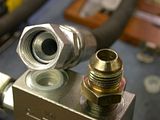  So that's all I did this weekend. Now the cylinder and hoses are ready to take up to camp where I will connect them to steel pipes. The steel pipes will run the length of the RC and upwards next to the 3pt top link. I will run hoses with QD's (also spares) from there to my rear remotes. This puts the hoses out of harms way, since the rotary cutter is notorious for slinging stuff that could sever them. But I'll have to do all that up at camp next weekend. Rob- |
|
3RRL
Administrator
Huge Kama
Posts: 2,027
|
Post by 3RRL on Mar 6, 2008 19:26:23 GMT -5
Here's an update which adds a new twist to this project. It will mean a little delay in finishing this one, but it sure will be worth it.
After seeing all those threads about gauge wheels, I've decided to use this contraption as gauge wheels for all my implements.
After all, the way it is designed and constructed, it is completely self contained and independent of the implement... including the hydraulic cylinder which moves the wheels up and down. I could move this wheel frame assembly from implement to implement by just removing some pins. They will attach quickly with little effort. Each implement would have hydraulically controlled gauge wheels.
They will be known as "QUICK CONNECT GAUGE WHEELS"
Rob-
|
|
3RRL
Administrator
Huge Kama
Posts: 2,027
|
Post by 3RRL on Mar 6, 2008 19:32:33 GMT -5
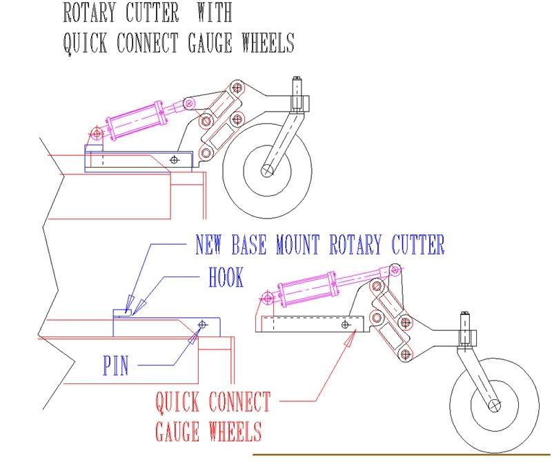
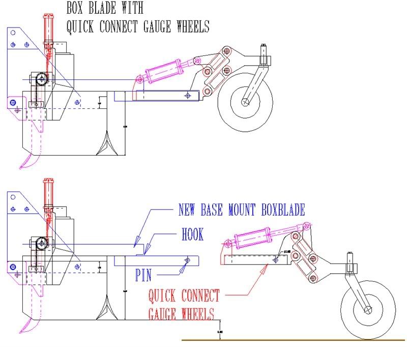
Ok, after considering several suggestions, I decided to draw the receiver base that accepts the Quick Connect Gauge Wheels assembly. It can be welded or bolted to each implement. Since the implements vary in size and function, each will have a separate base. This is to get the wheels to the ground and to get the proper amount of adjustment for each implement. The way it attaches to each implement has to vary a little also, so they might end up unique for that implement, but where it accepts the wheel assembly is all the same. So the receiver base design has to be simple and inexpensive. Here is the concept for the Rotary Cutter and for the Box Blade. 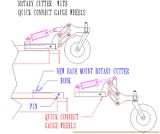 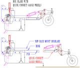 You can see they are a little different the way they have to attach to the implement. The receiver base will be made of 2 bars (dark blue) that fit inside the tubing of the wheel assembly. On one end, there will be a hook or slot that accepts the wall of the tubing. the other end, closer to the wheels has a hole for a 1" diameter hitch pin. So the gauge wheels slide on top of the receiver base until they butt up to the end of the slot, then the holes should line up allowing a large pin to fasten it. The hook or slot won't let it tilt up, and the pin won't let it get out of the hook. It can't go sideways because the wheel frame is like an upside down channel "U" shape. It's a simple locking device. Rob- |
|
3RRL
Administrator
Huge Kama
Posts: 2,027
|
Post by 3RRL on Mar 6, 2008 20:56:47 GMT -5
|
|
3RRL
Administrator
Huge Kama
Posts: 2,027
|
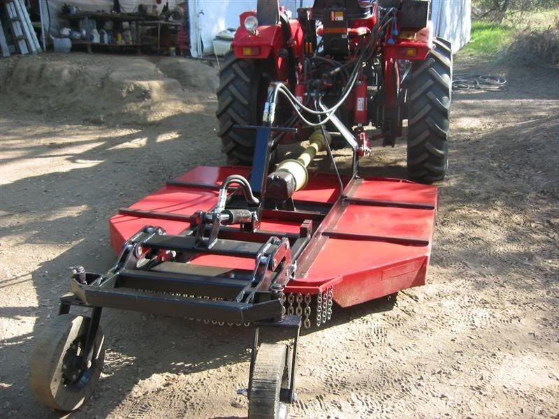
Post by 3RRL on Mar 6, 2008 21:00:06 GMT -5
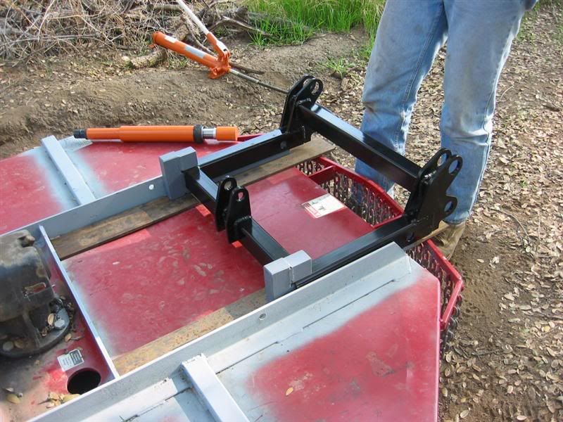
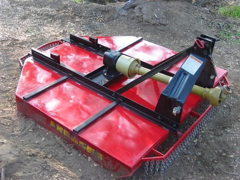
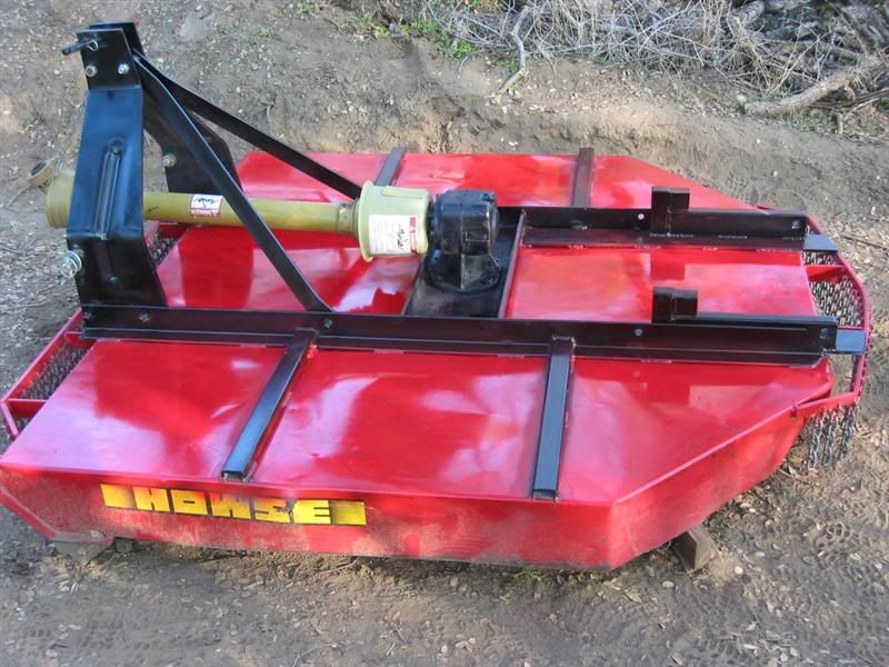
Here are a couple close ups of the system and also a video of it hooked up and working. I thought it turned out pretty good. Rob- 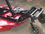 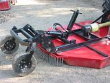 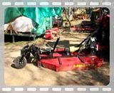 |
|


 ). The red thing in the port is a plastic threaded plug to keep chips out.