|
|
Post by Ronmar on Feb 14, 2008 22:53:56 GMT -5
Small Update: Ron, I have no idea what size fuses I would need do you have any idea? KIDD  No problem, as for fuse, Watts are Watts. Power in Watts(P) = Current(I) X Voltage(E). Conversely Power divided by voltage = Current or Power divided by Current = voltage. If you know any two values, you can solve for the third. Not accounting for inverter efficiency, 5000 divided by 12V = 416.6Amps But since the inverter is at best 90% efficient(probably most efficient at full load), it will take 10% more wattage from the batteries than is delivered in AC output, so 457.6A from the batteries for 5KW output from the inverter. I would guess the circuit protection on the inverter is around 460 amps, and each battery fuse should be 1/8 of that or around 58A. Ideally at that rate, your 1072 AH battery bank should last 2.3 hours... Unfortunatly that 134AH rateing on those batteries is probably for a 20 hour rate. Discharging at a significantly higher rate, you will loose a fair ammount of efficiency to heat in the cells and wiring. At that 458 A rate, I would say your 1072AH bank will only deliver 750AH, or about 1.6 hours at a 5KW load. A 20 hour rate for your 1072AH bank will be about 53.6A. So to get your full measure of current, after inverter efficiency correction, will be around 580W from the inverter for 20 hours, but the inverter is less efficient so you will get less than that due to higher inverter losses, maybe only 500W. That is the rub with 12V systems, the higher current draw requires monster cables to feed adequately without huge heat losses. Myself personally if I was going to power more than 1KW with an inverter, I would go to a 24 or 48VDC bank, preferably 48V. I would make this bank with 4 of the largest AH 12V batteries I could afford placed in series. The same 5KW output from a 90% efficient inverter would only draw 114A of current. this would need smaller wire and only a single fuse at the inverter, so much more simpliified wiring and not as many of the issues associated with maintaining and charging batteries in parallel. Ideally that size load should be fed with a 2300AH bank(114A x 20 hour rate) to draw at the most efficient 20 hour rate, but those are some monster batteries... Ron |
|
biggkidd
CTW Expert
 A World Away!!!
Posts: 226
|
Post by biggkidd on Feb 15, 2008 11:49:40 GMT -5
Hey Thanks Ron Are you an electrician or specialist? You seem to have a vast array of knowledge. The inverter has a serge capacity of 10000 watts. And I am actually using all 16 batteries linked together. So I am thinking I need 60 AMP fuses at each battery and a 500 amp fuse at each line into the inverter. Does that sound about right? The cables to the inverter are 1/0. That is whats recommended for that inverter. The only reason I went with 12V was price. The inverter was only $419.00. You were exactly right about the efficiency being 90% at max load. But this system should work well for something I have about $1000.00 invested in so far. I did get the HF 45W solar kit last night to hook in to keep the batteries topped off when we are gone for long periods. It will also cut down a little on charge time. If I can get this set up the way I am hoping I will have a weeks worth of power between charges with no more than we use. I will post a bunch more next week as we are leaving to go out of town now. KIDD |
|
|
|
Post by Ronmar on Feb 15, 2008 21:53:53 GMT -5
Kidd
I am a Chief Electronics technician in the USCG with 24 years experience in this field.
If you are using all 16 batteries, your fuse estimates sound about right. The only issue you might see is that if you pop one of the 500A fuses on one bank, a surge load over 5500W on the inverter will probably pop the one on the other 8 battery bank as well.
Using both banks puts you over 1KW of available power from the inverter at the optimum 20 hour discharge rate. You can do a lot with a KW:)
Ron
|
|
biggkidd
CTW Expert
A World Away!!!
Posts: 226
|
Post by biggkidd on Feb 20, 2008 19:09:39 GMT -5
Hey Ron, Thanks for all the info. Wow 24 years with the coast guard cool. I always thought that would have been an interesting carer. I have yet to see the amp gage on the inverter have enough draw to even register. The lowest led is for 120 amps and goes to either 500 or 1000 I can't remember.  When I was putting this system together my biggest concern was to make sure that anything I needed to run would have start up power with other things running. The odds of us using the whole systems power at one time is slim. With what we have as far as electronics go at camp including tools is fairly low. With wise power usage this should work just fine for years to come. I hope... I also added a HF 45 watt solar kit into the system this weekend. 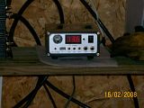 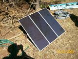 I don't have the panels in there permanent location at this time. They are hooked up and left running. This is mainly to make sure the batteries stay topped up when we are not there. One other thing the kit came with 2 12 volt 5watt cf lights that seem right nice. I have one of them hooked up in the power shed and it gives off plenty of light for that small space. (after it gets warm) Now Nickole is bugging me to put the other one over the sink in the camper. There is no light there. Thanks Kidd |
|
biggkidd
CTW Expert
A World Away!!!
Posts: 226
|
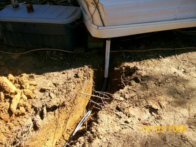
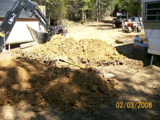
Post by biggkidd on Mar 2, 2008 22:39:15 GMT -5
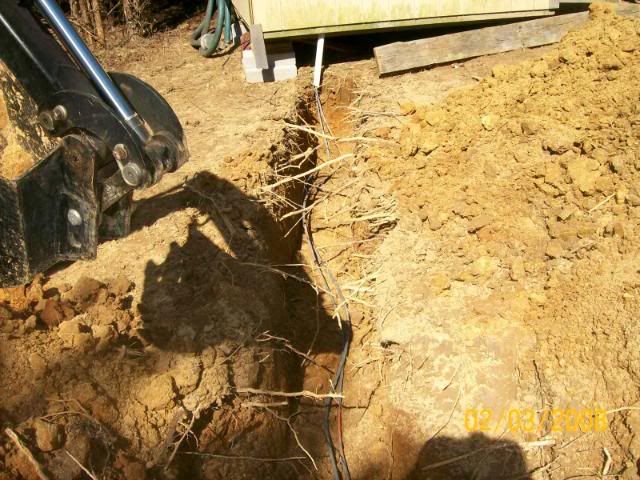
I got the power (service) cables in the ground today. For this I had to dig a trench from the building to the camper. I also buried an extra cable set to run 12V DC. We have a few 12V items running. That cheapo inverter seems to work real well.    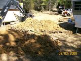  Thats the direct bury cable. 6666 aluminum. The trench is about 20-24" deep. I did use a old piece of 1.5 PVC to keep from damaging the cable with a weed eater. I put a short piece between the ground and the building and trailer to protect the cables inside. I haven't hooked anything up yet. Thats a rainy day project. Until then we can keep running the 12 gage extension cord. On another note we only had to run the charger once this weekend. ;D  ;D Good news. We got down there Fri. night and ran until this morning and still had 12.5V. We had the fridge running 3 to 5 lights and ran the microwave a few times. I also ran the lower hose heater on my tractor twice for about an hour both times. Thats forgetting that I used my porta band a few times. The batteries said 13.4 when we got there. I did have the 45 watt solar kit from HF on. I leave it hooked up running all the time. I almost didn't recharge the batteries at all. I don't know if the solar kit would have them recharged in a 5 day period or not. But I bet I'll find out before its all said and done.  One thing thats got my curiosity up is I checked the amperage on the solar panel today and its only doing 2 amps.  It should be doing 3 amps. I wonder if one of the panels is not working? Thanks for looking KIDD |
|
GuglioLS
Administrator  Jinma354 LE
Posts: 1,276
|
Post by GuglioLS on Mar 3, 2008 1:15:35 GMT -5
Nice! When you measured the 2 amp's out of the solar panel what was the voltage? (amps X volts = watts) maybe the batteries were not low enough to draw the full 3 amps? Think of the power coming out of the solar panel as very slow running water (Amps) filling up a large bucket (batteries) Just for arguments sake, lets say you got 8 hours of full sun at 45 watts for 5 days. 8 hours of sun, times 5 days = 40 hours. 40 hours times 45 watts = 1800 watt hours. Thats 1800 watts for one hour, or 180 watts of power for ten hours. As big as your system capacity is, 45 watts is not much. I think your home made alternator charger is ~ 70 amps? 70amps X 13.8 volts = 966 watts (20 times more output than the solar charger). You would need 20 of those Harbor freight solar panels to equal the output capacity of your gas engine charger. You have 16 of those 100 amp capacity batteries in parallel so that adds up to 16,000 amps  that's enough to vaporize anything conductive in a millisecond! Be carefull! Lets say all the batteries were completely dead, you would have to run your generator charger for 16 hours to fully charge them, the single 45 watt solar panel would take 44 days @ 8 hours a day. How much fuel per hour does the gas battery charger use? It might be more cost effective than more solar panels? At my house, we use 1000 kilo watt hours per month, if my math is correct 1000 kilo watts is one Mega Watts or about as much as a small tactical nuke. Maybe you can get a surplus watt meter, the kind that would normally be hooked to your house to measure power consumption. Something like that may help you determine how long to run your gas charger to charge the batteries. Larry |
|
|
|
Post by linus69 on Mar 3, 2008 10:33:41 GMT -5
|
|
biggkidd
CTW Expert
A World Away!!!
Posts: 226
|
Post by biggkidd on Mar 3, 2008 12:48:34 GMT -5
Larry, Nice!Thank you! When you measured the 2 amp's out of the solar panel what was the voltage? (amps X volts = watts) maybe the batteries were not low enough to draw the full 3 amps? I think it was 13.4 but I am not sure. One thing the solar charger and my multi meter read differently. I also think that was after I had run the gas charger when I checked. I left it to finish charging off the panels. Think of the power coming out of the solar panel as very slow running water (Amps) filling up a large bucket (batteries)Got ya. Just for arguments sake, lets say you got 8 hours of full sun at 45 watts for 5 days. 8 hours of sun, times 5 days = 40 hours. 40 hours times 45 watts = 1800 watt hours. Thats 1800 watts for one hour, or 180 watts of power for ten hours. As big as your system capacity is, 45 watts is not much. I think your home made alternator charger is ~ 70 amps? 70amps X 13.8 volts = 966 watts (20 times more output than the solar charger). You would need 20 of those Harbor freight solar panels to equal the output capacity of your gas engine charger. So my little gas charger isn't so bad after all? You have 16 of those 100 amp capacity batteries in parallel so that adds up to 16,000 amps that's enough to vaporize anything conductive in a millisecond! Be carefull!Sure enough a lot of power there. But wouldn't that be 1,600 not 16,000 amps? Yes definitely careful. Lets say all the batteries were completely dead, you would have to run your generator charger for 16 hours to fully charge them, the single 45 watt solar panel would take 44 days @ 8 hours a day.Boy you sure know this math front and back. Thats not bad if I can charge the batteries from dead in 16 hours. We have yet to come close to killing the batteries. After running them 2.5 days we still had 12.5 volts. I am not sure what to call 100% charge though. When I got the batteries they came up at 13.1V. When we got to the camp Fri night they were 13.4 V. I am figuring 12.0 V as being dead. Does that sound about right to you? How much fuel per hour does the gas battery charger use? It might be more cost effective than more solar panels?Far as I have been able to tell its burning about 1 gallon every 3 or 4 hours. Thats not exact but close enough. It does take a while to recharge but not to bad the worst thing is the noise. I try to plan it so I am not right there or making noise myself. Its a shame to ruin the piece and quiet out there with an engine running. One thing I noticed this weekend was the + connection was hot it had just a little corrosion on it. When I checked to see how many amps the charger was doing it was around 30. I stopped it and cleaned the connection and started it back up and it was charging 55 amps and cold to the touch. There was so little corrosion that I couldn't even see it really. It just looked like dull metal. Took a little sand paper to it and then it had a little shine. As to the gas being cheaper than solar panels it might be but with the way its going up and figuring over the next 30 or so years. At my house, we use 1000 kilo watt hours per month, if my math is correct 1000 kilo watts is one Mega Watts or about as much as a small tactical nuke.Amazing the different uses of energy. All at one time and you have a big boom. If its spread out you have light heat power & more. Maybe you can get a surplus watt meter, the kind that would normally be hooked to your house to measure power consumption. Something like that may help you determine how long to run your gas charger to charge the batteries. Man that would be great. Can you buy them anywhere? Or does it have to come from the power Co.? Then I would know just what my power is costing me. Also it could be used as a tuning agent. Thanks for the comments. This project has been a blast. I am learning so much. I had never in my life considered making my own power system until we saw just how far out we wanted to go. The almighty dollar got to talking and we had to listen. Of course there is also the fact we got twice as many acres for less money than just 20 miles closer to Richmond. Paul, I couldn't get the link you posted to work. We do plan to use some of the small wind turbines. I think we have one or two ok spots for them. What stinks is I am going to have to move the power station at some point. I just need to know where everything is going to end up to know where.  KIDD |
|
|
|
Post by Ronmar on Mar 3, 2008 21:04:06 GMT -5
IF you can answer a few questions, I might be able to offer some suggestions to improve your charger efficiency. First off an auto alternator is not especially eficient, at only about 50%. Then there are the losses with a "V" belt drive...
In the pics you posted, the engine and alternator pullys look to be about the same size, Do you have the measurements for the pullys? I am assuming that the engine runs at about 3600 RPM. What is it's rated HP? What is the alternator rated output(70A, 100A?)?
Alternators output their peak near their max RPM, around 5000-6000 RPM. The Claw Pole design of the rotor allows them to spin this fast and makes for a compact lightweight package. It is also that claw pole design that reduces their efficiency(requires more excitation current for a given output). Unfortunatly efficiency also goes down as RPM increases.
Rule of thumb for sustainable power generation with an engine is 2HP per KW of electrical output. 14V X 70 Amps is 980 Watts. That engine only needs to provide 2HP at that alternator output. It might be possible to run the engine at a lower RPM(different governor spring on the air vane?) and use a larger pully on the engine output to still get 4000-5000 alternator RPM. Less fireings per minute = less fuel burnt, up to a point. It would certainly reduce the noise output from the engine.... Failing that, if the engine is 4 HP or so, adding a second alternator would make the best available use of the HP and half your charging run times.
An idea I have heard about for noise reduction is to build a cinder block box around the engine, like you did around the wood heater you built. Fill the holes with sand. This will dampen the direct mechanical noise and direct it upward. That little exhaust deflector on the muffler can be removed(drill out rivets) and weld on a straight pipe. Slide this pipe into a hole in the side of a larger container(expansion chamber). It dosn't have to be a tight fit, as you want some room to allow for vibration/movement. An old 5 gallon steel pail or old "recycled" propane bottle, with an exhaust pipe running upward several feet . All of this set inside the cinder block enclosure. This again will dampen the exhaust pulse and direct it upward. You of course need to not impede the exhaust flow away from the cylinder head, so all added pipe must be larger than the stock opening. You also need to leave a few gaps low down in the block enclosure to allow fresh air in easilly for cooling.
Because of the efficiency losses with a belt drive auto alternator, you might actually be better off in the fuel used department with a small AC generator feeding a DC power supply/chargrer. The AC generator is going to be 85%+ efficient and a DC charger is going to be somewhere in the 90% range for an overall efficiency in the 75% area? That would be 25% less fuel burnt right off the top...
Ron
|
|
biggkidd
CTW Expert
A World Away!!!
Posts: 226
|
Post by biggkidd on Mar 3, 2008 23:15:51 GMT -5
Ron, Great info. I have 2 more of those 70 amp alternators. The engine is a 5.5 HP. The pulleys are 2.3/4" on the alt. and 3.5" on the engine. The tip about only needing 2 hp per KW is good stuff. I wasn't sure if that engine could handle another alt.. But now I know it can. I switched away from the generator because a 40amp battery charger I was having to run on my 3500 watt gen. and taking 8 hours to charge using a lot more gas. That gen uses about 1/2 to 3/4 gal an hour its pretty old. If we could set it up so the high use times and charge time are at the same time it would be ok but things just never work out. Thanks for the info now I have to bring my charger home and put another alt. on it. About the noise its not to loud just continuous. I have several ideas for muffling it but other things need doing first. I will keep the block idea in mind. I am kind of partial to this system any ideas on better alternators that will last a long time and have a higher out put. I would like to end up with 400 amps or more in the end. And I am a lover of the K.I.S.S. method. This is great now I can double my charging ability still using what I have on hand. ;D ;D ;D ;D ;D Thanks KIDD |
|
|
|
Post by Ronmar on Mar 4, 2008 19:50:31 GMT -5
OK, assuming that it is a 3600 RPM engine. with a 3.5" primary and a 2.75" secondary pulley that is a 1.27:1 ratio, so 3600 engine RPM will yield 4581 alternator RPM, which isn't too bad. What kind of current output are you getting from that alternator?
I suppose it is probably easier to change primary pulley size than the secondary pulleys on the alternators. If you were to increase the primary pulley size to say 4.5", then that divided by the 2.75" secondary pulley would yield a 1.64:1 ratio. You could then lower the governed engine rpm to around 3000, which I would guess would still net you 4+ HP out from the engine. 3000 X that 1.64 ratio would deliver an alternator RPM around 4909 and still provide enough HP to drive two alternators.
That would take 1/6 off your engine RPM, so in theory, that should cut your fuel consumption for a given load by approx 1/6th. With that size primary, you would have to reduce the engine RPM a bit as a 3600 RPM primary RPM would get you just over 5900 alternator RPM, and that is pretty fast. The governed engine RPM is usually determined by a spring that plays tug of war with an air vane. These two forces reach equilibrium at the governed RPM. Changing that RPM is usually a matter of changing the spring for a lighter spring which will allow the air vane to win the tug of war at a lower RPM. The beauty of this is that if it doesn't work out, you can easily swap pulley's and springs back to what you have now and the 4500 alternator RPM.
You might also be pleasantly surprised at the noise difference that 600 fewer RPM make. The larger pulley would also allow for more belt contact surface area as you will have to open up the belt angle around the primary pulley in order to run it around a second alternator pulley.
Be sure you are spinning the alternator the correct direction. They will output in both directions, but they will only draw cooling air thru the case to the fan/pulley end when spun in the correct direction. I can't quite tell from the pic you posted which way the vanes are orientated. but the blower assembly behind the pulley has tabs folded down toward the alternator case to form air vanes. When spun in the correct direction, the outer end of the vane farthest out from the shaft will lag behind the inner end of the vane. This pushes air outward and creates a low pressure in near the shaft. This low pressure is made up by drawing fresh air in thru the case from the end openings opposite the pulley. IF spun backward, they only move a fraction of the air thru the case(more efficient to pull air than to push it).
Output is VERY dependent on temperature. A hot alternator will not put out as much as a cold alternator. If you are monitoring your current out from the alternator, You have probably noticed that the amp output drops as it warms up. By adding a second alternator, you will be overall lowering the stress on each, so the output should be greater than double what you are currently getting, especially if you can get a few hundred more alternator RPM.
Ron
|
|
biggkidd
CTW Expert
A World Away!!!
Posts: 226
|
Post by biggkidd on Mar 4, 2008 20:21:56 GMT -5
Hey Ron, Thanks for all the info. I will bring the charger home this weekend. Then I will better be able to find out some of the answers to the questions you have brought up. I more than likely have the alternator back wards. I will bring it home and work on it some more. I will get back to you then. Thanks for the help. KIDD |
|
biggkidd
CTW Expert
A World Away!!!
Posts: 226
|
Post by biggkidd on Mar 4, 2008 20:59:33 GMT -5
Hey Ron, Just came back on to make sure I had this strait in my mind. The alternator should pull air in from the rear of the case and out through the fan at the pulley? Is that right? If so I have to redo my charger I am pretty sure its running in reverse. Thanks KIDD |
|
3RRL
Administrator
Huge Kama
Posts: 2,027 
|
Post by 3RRL on Mar 4, 2008 21:48:17 GMT -5
Ron,
I am totally impressed with the amount and detail of the information you are providing for Kidd. Your description of how to reduce the generator rpms to save fuel, and use pulley sizes to get added alternator rpm is pretty clever. Even I could understand what you were doing. I didn't know there was a spring that governs the rpm and the manner in which it works with the air vane.
Thanks for the detailed descriptions...
Very interesting stuff.
Rob-
|
|
|
|
Post by Ronmar on Mar 5, 2008 0:16:52 GMT -5
Hey Ron, Just came back on to make sure I had this strait in my mind. The alternator should pull air in from the rear of the case and out through the fan at the pulley? Is that right? If so I have to redo my charger I am pretty sure its running in reverse. Thanks KIDD That is correct. Here is a pic.  The arrows around the left hand diagram represent airflow. The right hand diagram is looking from the pulley end. The angled lines between the inner circle(pulley) and the outer circle represent the fins on the fan. If oriented as shown, that would be for a clockwise rotation as seen from the fan end. "Nature abhors a vacuum" Think of the fins like snowplows, the angle and centrifugal force push the air outward, ejecting the air radially as the pulley/fan spins. The low pressure this creates in the center has to be made up from somewhere. The fan top is usually a flat plate, and the fins spin down close to the case, so not much air can get back in that way. The only other source to fill this vacuum is to draw in fresh air thru the case. If it is backwards, don't feel too bad. I have seen quite a few homemade generators and welders using auto alternators over the years. I would take a guess that probably 25% I have ever seen were initially setup with the alternator turning in the wrong direction. I even saw a guy install a prop on an ultralight aircraft backward once:) That was why I brought it up... Ron |
|


 ;D Good news. We got down there Fri. night and ran until this morning and still had 12.5V. We had the fridge running 3 to 5 lights and ran the microwave a few times. I also ran the lower hose heater on my tractor twice for about an hour both times. Thats forgetting that I used my porta band a few times. The batteries said 13.4 when we got there. I did have the 45 watt solar kit from HF on. I leave it hooked up running all the time. I almost didn't recharge the batteries at all. I don't know if the solar kit would have them recharged in a 5 day period or not. But I bet I'll find out before its all said and done.
 It should be doing 3 amps. I wonder if one of the panels is not working?
 that's enough to vaporize anything conductive in a millisecond! Be carefull!