3RRL
Administrator  Huge Kama
Posts: 2,027 
|
Post by 3RRL on Jan 27, 2008 22:28:19 GMT -5
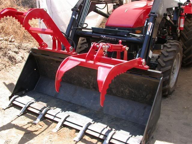
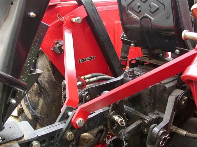
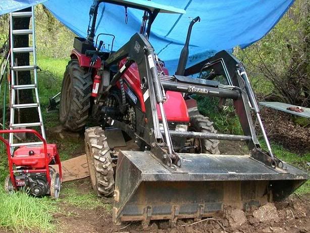
When I made my subframe for the Nardi backhoe ( see this thread Nardi Backhoe), I kept the original 3 pt mounts and added 2 lower (subframe) connections and 2 upper side connections. The benefits of a subframe mounted backhoe are obvious. Some 3 pt hookups have added side support going from the backhoe to the rear end or the rear hitch area. All this adds up to a lot of strength when the backhoe operates in-line with the tractor, but when digging off to the side a tremendous amount of sideways (torsional) pressure is placed upon the top link attachment. So I also added the top side brackets to help stabilize this torsional stress. Here's a picture of the backhoe, straps and subframe I made. Note that the 2 top side brackets are shown attached to where the top link attaches to the tractor, but they really attach to the 45° brackets that project slightly above the top link bars. 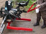 This next one shows how the top side brackets attach to the tractor's ROPS....definitely one of the strongest things on the tractor. (Don't start with the ROPS Cops business, been there ...done that aleady. LOL...) What that does is take most of the stress off the hydraulic box (top link connection) and places it right to the tractor via the ROPS. I figure if they're strong enough not to collapse during a roll over, they shouldn't budge from the backhoe pulling on them. You can also see the top link bar still pinned to the tractor top link connection. Can you say 7 point connection now? 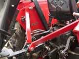 |
|
3RRL
Administrator
Huge Kama
Posts: 2,027
|
Post by 3RRL on Jan 27, 2008 22:29:19 GMT -5
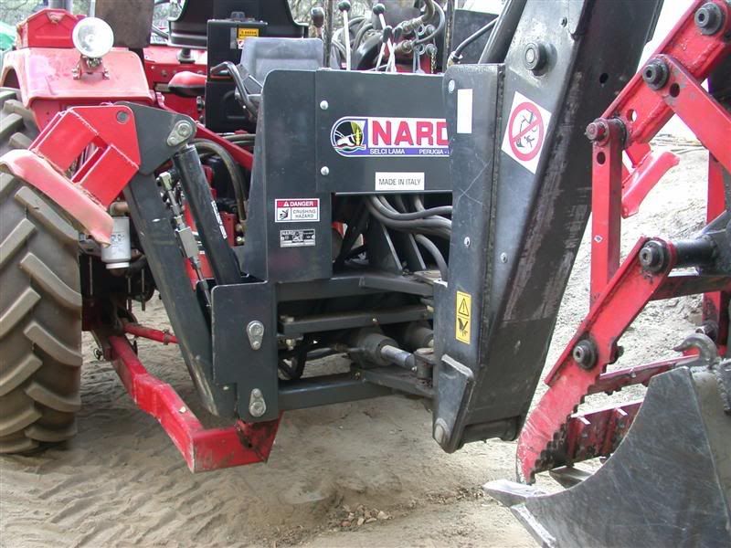
This last shot shows the backhoe sitting in the subframe and if you look closely, you can see the original 3pt is hooked up and also the top side brackets. Look closely and you can see the lift pins inside Pat's EZ Lift system (grey) just above the red sub frame arms. 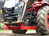  The subframe itself is welded to the loader frame, thus transferring all torsional stress to the tractor frame itself. A backhoe subframe is one of the best things you can do to prevent damage to your tractor. It should be pretty strong with the 7 point connection now. It only takes about 5 minutes to get locked on or take off unless Larry is helping.  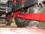 |
|
3RRL
Administrator
Huge Kama
Posts: 2,027
|
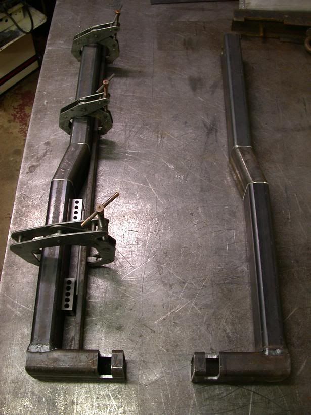
Post by 3RRL on Jan 27, 2008 22:29:51 GMT -5
Here are some particulars on the subframe. Before I made the final configuration, I laid out what I thought the part of the subframe that would be welded to the backhoe. I did this part at home and had to take it to the property to see if it would fit. 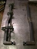 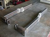 You can see the legs did not have the part that goes up to the bottom of the backhoe yet. The piece I'm talking about is the one you can see on the other photo above that the backhoe sits on. I had to measure at camp and then take them home again to make the final piece. |
|
3RRL
Administrator
Huge Kama
Posts: 2,027
|
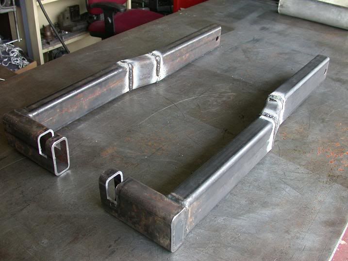
Post by 3RRL on Jan 27, 2008 22:30:50 GMT -5
When making the receiving subframe that is welded to the FEL frame, it is important to re-enforce the connecting holes. This picture shows how I machined 5/8" thick bar stock inserted into the ends of the subframe where they connect up. This was also done at home and brought up to the property before I welded them onto the FEL frame. 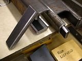 These pictures are close ups of the short legs that are welded to the loader frame. This ties the whole enchilada together ... the backhoe subframe to the FEL frame and to the rear end of the tractor. Notice the cut-outs in them where the legs from the backhoe frame fit in. There is also a hole where the two are pinned together. So the backhoe subframe is really a two-piece subframe. Part welded to the backhoe and part welded to the tractor. You can see from these pictures there's not a whole lot of room in there to tap the connecting pins in and out. Later, when I set the rear wheels at their widest, there was a lot more room under there.   |
|
3RRL
Administrator
Huge Kama
Posts: 2,027
|
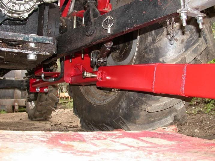
Post by 3RRL on Jan 27, 2008 22:35:27 GMT -5
The connection to the backhoe is welded on. I use ¼" wall tubing, 2" x 4" to make the subframe. That was the las attachment I made (to the backhoe). The hardest part was figuring out how to attach it to the tractor and the FEL frame. I had to do it all at my rural property in the Winter. Once I got it figured out, I had to route the subframe to miss the tractor's lower lift arms AND make it so I could still hook-up and pick the backhoe up with them so they do not interfere. I use them to lift the backhoe high enough to lock in the top side brackets so everything is under load equally. This is my working conditions up there. 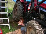 It's a wonder I even got them as good as I did. I had to measure up there (best I could with lousy tape measure) and bring same dimensions down South and machine what I could. Then take the compnents back up and try to fit and adjust them onto the tractor and backhoe. This process was quite involved and took a long time. 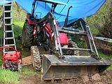 |
|
3RRL
Administrator
Huge Kama
Posts: 2,027
|
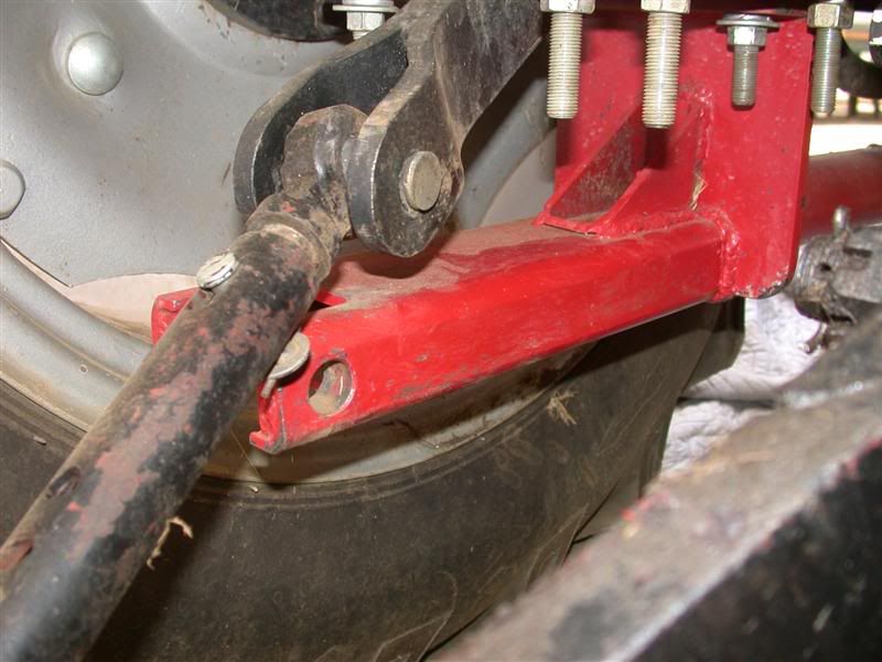
Post by 3RRL on Jan 27, 2008 22:39:21 GMT -5
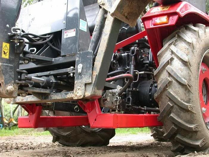
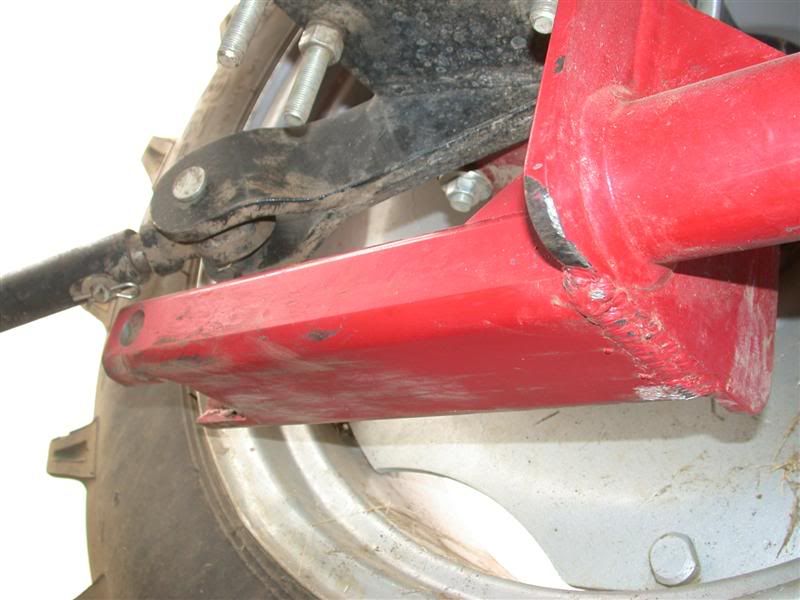
This one shows how the loader frame/brackets and the short part of the subframe are welded together. The short part stays on the tractor. You can see it on the right, behind the axle. 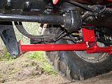 Here's a close up of the backhoe welded attachment. This part will fit into the short ones on the tractor and get pinned together. Considering I was still using the original 3pt mount, I tried to make all attachments as wide as possible to absorb as much torsional load as possible...wider then the 3pt lower arms afforded. 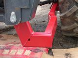 |
|
3RRL
Administrator
Huge Kama
Posts: 2,027
|
Post by 3RRL on Jan 27, 2008 22:48:48 GMT -5
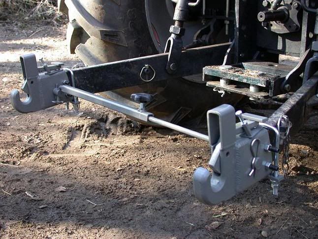
I wanted to make the connecting holes a pretty good fit so I drilled and reamed them .005" oversize for the Ø7/8" pins. This was to insure the subframe would act "solid" when pinned together. Of course, I was dreaming....it was way to tight a fit to realistically have them line up exact after welding and mounting the legs. They will go together only if I have everything lined up just right. That means using the 3pt lift arms, the backhoe stabilizers and the bucket to make it all line up. This can be pretty frustrating when I'm working in the mud or dirt floor of the tent. But I've gotten to where I can get it on or off in under 10 minutes now (5 minutes is my best time). Here you can see how the two are pinned together (same photo as one of the above) but shown again so you can see how I have to get to this connection. 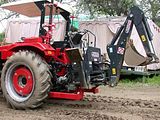 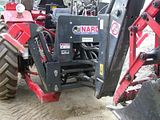 |
|
3RRL
Administrator
Huge Kama
Posts: 2,027
|
Post by 3RRL on Jan 27, 2008 22:49:22 GMT -5
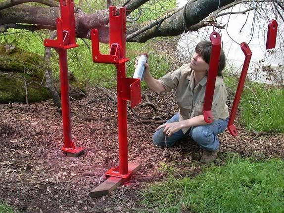
I guess I could have made the legs welded to the tractor longer and make the connection easier to get to, but I wanted as little of the subframe staying on the tractor as possible. I wanted to avoid bending them or filling them with mud when not in use. One thing though, since the pins fit so good, I have to tap them into the holes and then pry them out even when lined up. So the last thing I did was weld big old washers to the back of the pin heads. This leaves about 3/16" gap when the head hits the frame .... enough for me to slip a small hand pry bar in there and pry them out. Once they get about halfway out, they slip out easily. 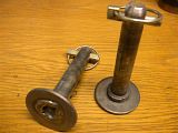 This last picture is of Loretta (yup, you guessed it) painting the loader frame and the short subframe legs after they were welded together. It gives you an idea how to fasten the short legs of the subframe to the loader brackets. Once welded together, they are like one unit.  I purposely did not post that picture before to avoid all the flack you guys are going to give me! Rob- |
|
|
|
Post by stumppuller on Aug 31, 2008 10:38:08 GMT -5
Nice Job. Impressive as usual. My approach to these remote, in-the-field improvements is to first select the size of the iron I'll be using. Then I rip some wood to the same cross sections as the iron. Haul the lumber up to the tractor and using screws, battery powered saws & drills cut-and-fit the wooden "iron" into a complete mock-up. Use the mock-up to cut & weld in real iron.
I realize that your improvement has some complex fit-ups and this approach may not be suitable, but for simpler stuff it works great. My stiffening bracket was made this way (see my entry of Aug 30 in this post) Now if I only had your welding skills I could really do some impressive stuff.
|
|