3RRL
Administrator  Huge Kama
Posts: 2,027 
|
Post by 3RRL on Jan 28, 2008 2:55:18 GMT -5
After I got my backhoe subframe completed (see this thread Building a Two-Piece Subframe), I started on another backhoe project. That was to design and build an articulating (moving) backhoe thumb. Before I start telling that story, here's a preview of how the moving jaws and bucket work together. It's all mechanical and driven by the same hydraulic cylinder that curls the bucket. This video shows how it's supposed to work. The hydraulics are disconnected for this preview. 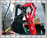 |
|
3RRL
Administrator  Huge Kama
Posts: 2,027 
|
Post by 3RRL on Jan 28, 2008 2:59:53 GMT -5
I've been wanting to make a "Thumb" for my backhoe for quite some time now. Among other things, I thought it would come in especially handy for placing rip rap rocks in my gutters just before the culverts. Many of the culverts are dug down beside the road and I could reach in there to place the rocks pretty easy with the backhoe. With that in mind, I started a small photo collection of different thumbs guys have made or bought for their backhoes. I got a lot of pictures but here are a few I "borrowed" from other threads. These are all fixed thumbs, and some can be adjusted to different positions. There are hydraulic moving thumbs too, but they need another spool valve and hose connections to operate. I wanted something different. 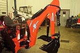 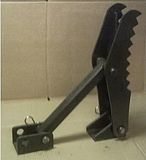 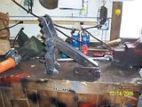 |
|
3RRL
Administrator  Huge Kama
Posts: 2,027 
|
Post by 3RRL on Jan 28, 2008 3:32:04 GMT -5
Since I installed the bucket grapples for the FEL (see this thread Dual Bucket Grapple Project), I don't need to pick up giant rocks with the backhoe any more. I'm looking for something a little more nimble and I came across this thumb that moves back and forth without using a hydraulic cylinder.  I thought that would be pretty cool to have one on my backhoe too. So I made up some sketches of how I would have to make pivot locations to make mine work that way. Fortunately, I had some pin locations and some other dimensions written down so I could try to figure it out, but as it turns out, I'm going to need several more measurements that I didn't think of. The trick would be to get the geometry, linkage and pivot points correct so I could use the motion of the existing hydraulic cylinder which activates the curl and dump on the backhoe. Anyway, here's a crude sketch of an idea I came up with and I think it will work once I get all the missing dimensions. 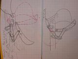 |
|
3RRL
Administrator  Huge Kama
Posts: 2,027 
|
Post by 3RRL on Jan 28, 2008 3:36:53 GMT -5
Realizing that the pivot point locations will be critical to get this idea to work, I started to lay it out on my CAD system. At this point, I had to guesstimate some of the shape and width of the backhoe components and these will have to be confirmed. But in any case, the concept seemed like I can get it to work on my backhoe. 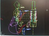 Using the concept, I rotated the linkage to different positions to see how they affect each other. I made several different attachment points and varied the connections on the articulating links to see what effect they would have. So I'm planning to have a couple of additional connection pivot holes in each link which results in the jaws closing slower or faster, opening farther or closer depending on the position of the bucket. I want to be able to pick stuff up when the dipper stick and boom are stretched out but also when they are folded, closer to the tractor. Having a couple of different pivot points will let me accomplish this. Here is another CAD picture showing the bucket as it rotates in and how the jaw starts to meet it. I can make the jaw meet the bucket by accelerating or delaying the jaw to allow more or less bucket curl...by moving the pivot points on the linkage. 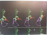 |
|
3RRL
Administrator  Huge Kama
Posts: 2,027 
|
Post by 3RRL on Jan 28, 2008 3:41:06 GMT -5
I'm went to the property tomorrow to do a bunch of work up there, but also to get the other measurements. I need to verify ... or change the drawing concept. In the mean time, the jaws are not going to change nor the articulating linkage. Only the connections to the backhoe dipper stick may have to change and of course the width of the pivot hole brackets that will be welded to the backhoe. I've chosen the jaws to be 12" wide, so the thickness of the linkage bars and hardened washer will require a certain width when it's all connected to the backhoe dipper stick. Anyway, I started machining the jaws by drilling out the shape. I used a black marker to draw the basic shape of the jaw from my CAD drawings. 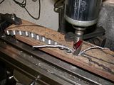 I dialed off center to center plus .005" to leave a super thin "web" between the holes so the pieces would not fall off on the last hole and catch my drill and bust it. Then I took a chisel and tapped the webs free. The remnant fell off and I had part of my shape. 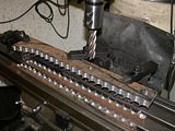 |
|
3RRL
Administrator  Huge Kama
Posts: 2,027 
|
Post by 3RRL on Jan 28, 2008 3:42:10 GMT -5
Then I stuck in a 1" corncob mill (roughing endmill) and started to cut the handle and radius on the piece. 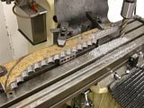 After that, I started to cut the radius on the back side of the tips of the jaws. Notice also that I milled off all the sharp ends on the teeth and left a 3/16" flat on them. 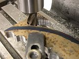 After milling, I went over to the dics sander and blended the cuts in. This way I was able to smooth out the surface and generate somewhat of a real radius on the handle and the curve on the back of the jaws. My blueprint was the black marker line.  |
|
3RRL
Administrator  Huge Kama
Posts: 2,027 
|
Post by 3RRL on Jan 28, 2008 3:44:31 GMT -5
After getting the jaws the way I wanted, I started on the linkage. There are 3 linkage bars on each side and I sawed and milled them to length, then drilled them for the all the pivot holes. I will be using ؾ" shoulder bolts for all the pivot pins. They have a 5/8-11 thread on the end and socket heads on the other. 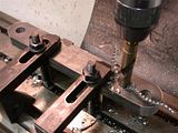 So after all that, this is what I got so far. 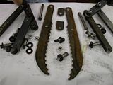 Oh, I also started to turn up the pivot bases that will be welded to the backhoe, but have not finished them. I needed to get the width of the dipper stick and the width of the actuating link on the backhoe so I can make the shoulder bolts bottom out without pinching the linkage. That required another trip to the property. Rob- |
|
3RRL
Administrator  Huge Kama
Posts: 2,027 
|
Post by 3RRL on Jan 28, 2008 17:02:19 GMT -5
I used the CAD to move the linkage and bucket from the pivot points in the picture in one of the first posts where there are multiple drawings of it. You can clearly see how the bucket and jaws are approaching each other.  It seemed to me the bucket and jaws approach each other to "grab" stuff. Does anyone see a problem where if I "curl" the bucket to grab something it will drop out? I've welded 2 plates across the jaws to help with stability and to catch stuff. 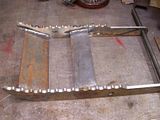 Maybe I should add some extra teeth on the plates ... kind of like a sharks mouth? I do have those drilled out remnants I could cut up and weld to them. Sort of like this, except I would make the rear ones lower profile. Or do you think adding them makes no sense and could just collect dirt? Does look pretty cool though? 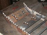 |
|
3RRL
Administrator  Huge Kama
Posts: 2,027 
|
Post by 3RRL on Jan 28, 2008 17:04:06 GMT -5
I had a chance to weld the extra rows of teeth to the inner plates. I had to machine the height down a little so they would not stick up above the outer teeth. They came out pretty cool looking. I also primed and painted the jaws and linkage and bolted everything together. I used Ø3/4" hardened shoulder bolts and Nylock nuts and hardened washers for spacing. I have it mocked up sort of like what it will look like once it's mounted to the dipper stick. Never mind the unpainted bars, they are there only so I could prop it up. The front white pieces will be welded to the dipper stick, under it and about 4" away from the bucket pivot. The middle white round pieces will be welded to the moving kidney shaped arm (attached to the hydraulic cylinder) which powers the linkage. And the back white round pieces will be welded to the side of the dipper stick. Here is what it looks like now: 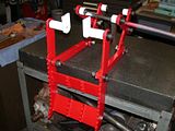 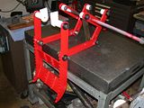 |
|
3RRL
Administrator  Huge Kama
Posts: 2,027 
|
Post by 3RRL on Jan 28, 2008 17:08:29 GMT -5
Got back from the property and got my thumb mounted to the backhoe. Man, it sure looks nice even if I do say so myself. I took several photos and a couple of videos to show you guys. Unfortunately, my tractor wasn't running so I could not try it out on the real stuff. But the whole concept was there and the Mechanical Thumb and bucket moved together as designed. First thing I did was decide where to mount the pivot on the kidney shaped actuating bar, which is attached to the hydraulic cylinder that moves the bucket. In my drawings, I had the distance at 4" from the pivot pin. so I scribed a radius and found center on each side. Then center punched and had to pick a pilot drill from my new Harbor Freight 119 piece drill set. ($39 bucks) 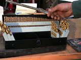 Next had to drill the 17/32" tap drill through the 3/4" thick pieces. That was quite a job for an old dude like me. 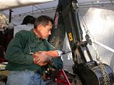 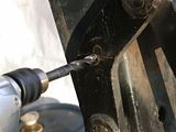 Then I lined up and clamped the pivot blocks to the bars and tapped them 5/8"-11 thread for the Ø3/4 shoulder bolts. 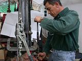 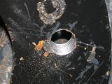 And here is the first one bolted on the kidney shaped arm. Later on, I will weld them on solid. You can see when the shoulder bolt is run home there is exactly enough room for the linkage and washers plus some running clearance (about .030") 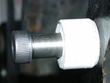 |
|
3RRL
Administrator  Huge Kama
Posts: 2,027 
|
Post by 3RRL on Jan 28, 2008 17:25:39 GMT -5
With the first point established, I could hang the articulated assembly from it and start figuring out where to put the two other points. Actually three if you count the rest position pivot. I used my CAD drawing as a guide, but would ultimately make my choice after checking all positions, including the resting position when not in use. 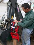 Here you can see the multiple clamps I had to use for positioning. That was a major drag holding up the pieces and trying to clamp them at the same time. 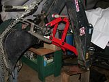 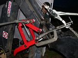 Loretta helped the entire time or I would never have been able to mount the darn thing. We ended up moving the pivot locations slightly from the CAD drawing to accommodate all positions and the desired acceleration for the jaw to close. We also checked the "rest" position and even made sure the tips and bucket teeth matched up perfectly. 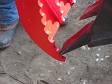 |
|
3RRL
Administrator  Huge Kama
Posts: 2,027 
|
Post by 3RRL on Jan 28, 2008 17:27:43 GMT -5
Well, you can imagine the clamping nightmare because not only did we have to get all the pivots clamped to the dipper stick, we also had to be able to move the jaw AND bucket to be certain we had chosen the right pivot locations. So the clamps had to be out of the way of movement. You can see above that we used a 24" Crescent wrench to clamp to so we could hold the jaw pivots to the bottom of the dipper stick! I tapped them all around and measured best I could to make sure they were all aligned. If it all works out, then I will start welding them right where they're clamped. Here is a video of the moving thumb while it is still clamped. I released the pressure on the hydraulics so I could move the bucket. I still had the chain and come-a-long on the bucket in case it crashed. I also was happy to see there would be little rolling action, if any at all. With the two moving together, it would "grasp" or clamp an object very quickly. It turned out pretty good so the next step is to weld all the attachments ... YIKES. 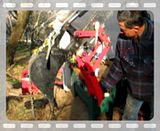 |
|
3RRL
Administrator  Huge Kama
Posts: 2,027 
|
Post by 3RRL on Jan 28, 2008 17:28:57 GMT -5
Satisfied with the positions, I looked for some 6011 rod to use with my Lincoln 225 arc welder varying the amp setting between 180 and 200. I run it off a Generac Wheelhouse 5550 generator. 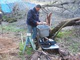 This is my workshop, so it is not the best conditions to screw something up. It's not like I'm working in my garage shop or anything like that. It was another cold day with rain in the forecast. 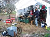 I started my first weld. I could not move the backhoe to lay it down for every weld, knowing I would challenge my OP welding ability for this project. 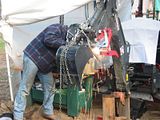 Here's the first pivot welded on. It didn't turn out too bad going all the way around it. I was happy. 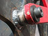 |
|
3RRL
Administrator  Huge Kama
Posts: 2,027 
|
Post by 3RRL on Jan 28, 2008 17:29:55 GMT -5
Some more overhead welding and the results. Overall, I was very pleased with how all the welds came out. 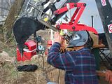 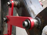 Here a shot of the whole thing welded on from the back of it. 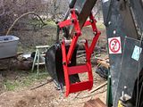 |
|
3RRL
Administrator  Huge Kama
Posts: 2,027 
|
Post by 3RRL on Jan 28, 2008 17:30:48 GMT -5
Then it was time to take everything back off and re-paint. This, of course was done by Loretta. She cleaned and painted the dipper stick and the linkage too. Notice in this picture the added pivot for the "rest" position. 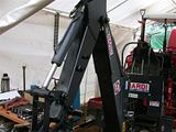 Here's the thumb and linkage drying.  And Loretta and Coco taking a break from all their work.  |
|