quikduk
CTW Life Member
   Dog House
Posts: 552
|
Post by quikduk on Aug 4, 2009 14:10:23 GMT -5
I have re-started our driveway gate project after having purchased the bulk of the materials and operator over 18 months ago… FWIW, here is the design strategy: 1. operator will be a large linear actuator capable of 90 to 110 degree opening with solar power but be future line voltage ready 2. gate will be a three panel, 4-rail, single swinging (in-swing) 17’-7” gate designed to resemble the adjacent 3-rail vinyl corral fence 3. hinges will be 1-1/4” aircraft grade Heim joints with 1” grade 8 fasteners 4. gate must weigh between 350# and 450# with a safety factor of at least 20% 5. the gate and fencing will have brick wrapped and lighted pylons between each end condition with an integral address sign 6. the gate must have a family “brand” or “logo” Here are some photos of the progress to date. 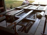 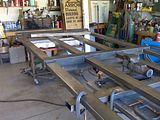 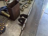 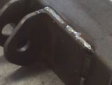 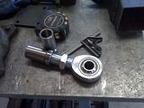 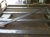 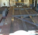 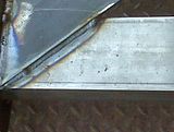 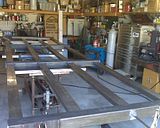 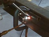 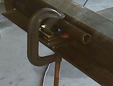 The hinge post is also welded and is awaiting final design “tweaks” before being sand blasted and powder coated. I then have to start digging the foundation which will be a 36”w x 48”l x 66”d hole. This will require about 2.6 yards of concrete. Once the gate hinge post is set, I will temporarily hang and power the gate so I can determine the locations of the two capture posts. These will then get built, finished and installed before the gate received its final modifications and finish. After all of this is finished, I have to build the 36”sq. x 66”h brick wrapped concrete block pylons, fabricate and install the “brand” on the gate and add lights and address numbers. More updates to come… |
|
GuglioLS
Administrator  Jinma354 LE
Posts: 1,276
|
Post by GuglioLS on Aug 4, 2009 16:49:57 GMT -5
Looks great Ken, For some reason the photos are not opening up for me, must be photobucket on the fritz ATM. "After all of this is finished, ................SNIP..............fabricate and install the “brand” on the gate and add lights and address numbers."Got a design in mind for the gate "Brand"? If you send me an autocad DXF or DWG file I can plasma cut it for you. That is if it's not 8 feet long.  plasmaspider.com/viewtopic.php?f=6&t=444&p=992#p992 plasmaspider.com/viewtopic.php?f=6&t=444&p=992#p992Larry |
|
GuglioLS
Administrator  Jinma354 LE
Posts: 1,276
|
Post by GuglioLS on Aug 4, 2009 20:56:24 GMT -5
This could be plasma cut:  Perhaps welded onto a Crest or Coat of Arms? Larry |
|
quikduk
CTW Life Member
   Dog House
Posts: 552
|
Post by quikduk on Aug 5, 2009 10:21:55 GMT -5
That is cool Larry. I am thinking it will be a 20" dia circle with 4 letters combined inside. I haven't decided if I want to have the address number and street name around the circumference and captured by the ring yet.
I have the logo "sketched" but need to put it in the computer.
I was thinking it could be cut out of 1/4" plate which I would then have powder coated. I would then use "nut-certs" into the middle two, middle gate tubes and bolt it to the gate with pin head SS torx screws and blue Loctite.
If the estimates locally come back too much, I'll be sure to give you a call and we'll work out the price and shipping and thanks again for the offer.
BTW, Hi to Esther!
|
|
GuglioLS
Administrator  Jinma354 LE
Posts: 1,276
|
Post by GuglioLS on Aug 5, 2009 11:17:49 GMT -5
Hi Ken,
IMHO after plasma cutting several signs, logo's and other ornamental items 1/4" plate is kind of thick for that sort of thing. personally I would go with 1/8" or even 14 ga. to save on weight, material and shipping costs. Powder coating is the ticket for sure. Your an accomplished architect adept at CAD programs, so I'm sure what ever you come up with will be totally awesome. Keep in mind plasma cutting this sort of thing requires at least a .250" space between lines or adjacent cutouts so the plasma cutting does not burn over into the next line. Of course that's not an issue with laser or water-jet cut parts. Just my .02 cents worth. Esther says hi back at you and hi to J too.
Larry
|
|
quikduk
CTW Life Member
   Dog House
Posts: 552
|
Post by quikduk on Aug 5, 2009 14:12:52 GMT -5
Thanks Larry. I think you are right that 1/8" would be strong enough and thanks for the clearance tip. I'll keep that in mind when I am either drawing this.
|
|
quikduk
CTW Life Member
   Dog House
Posts: 552
|
Post by quikduk on May 14, 2012 22:44:40 GMT -5
Talk about resurrecting a dead thread...
Larry G asked how it went and I have to say...it hasn't gotten much further. I have sandblasted the gate and hinge post and they are awaiting the painting and installation. I elected to use Rustoleum industrial grade white paint and spray it myself. This way, if I have to modify or repair anything, touch up is a breeze.
The work is waiting on funds and my recovery but will likely start up again in earnest in the next couple of months.
I'll be sure to take and post descriptive pics when we get started again.
I sure hope my archineering is accurate...
|
|
quikduk
CTW Life Member
   Dog House
Posts: 552
|
Post by quikduk on Jul 11, 2013 17:39:39 GMT -5
Whoa...necroposting again. My recovery took over 15-1/2 months before I was cleared to go back to work. As of April 4, 2013, it became one year since my successful back surgery. It is now July 11, 2013 and I am finally starting to be able to do actual "work" around our property. It sure took a bit longer than expected but now that I am up and around and functioning reasonably well, I will post an update. The gate project is once again in full...er...swing... Here are some recent photos of the post, hole and installation. 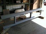 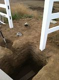 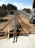 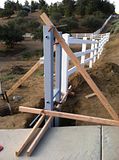 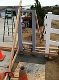 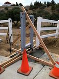 The footing is 36”x48”x55” as I decided to keep the gate a little higher than the fence line so that the brick wrapped pylons/columns will be taller. The concrete is 4000 psi with 1” rock and 4” slump as this is a structural issue. The present calcs. on the gate show that it currently weighs in at 344# with the hinge post at 342# and the footing weighs in at around 8250# and each of the brick wrapped columns should weigh in at 8100#. Whew! Once this footing sets up (28 days), I will hang and adjust the gate so I can determine the locations and specs. of the two capture posts. |
|
quikduk
CTW Life Member
   Dog House
Posts: 552
|
Post by quikduk on Sept 26, 2013 14:34:25 GMT -5
|
|
|
|
Post by bradblazer on Oct 1, 2013 18:44:27 GMT -5
Hi Ken, It's nice to have you back! Really sorry to hear you've been laid up all this time. The gate is looking great!
|
|
|
|
Post by linus69 on Oct 4, 2013 7:59:44 GMT -5
Looking good Ken, I`m glad to hear you are back in harness again and feeling good.
Paul
|
|
quikduk
CTW Life Member
   Dog House
Posts: 552
|
Post by quikduk on Oct 9, 2013 11:02:37 GMT -5
Thanks Brad and Paul. Yeah, the injury, surgery and recovery sent me for a pretty big loop. I am slowly trying to build my strength back and grateful every day that I can still walk. Now I have to finish all of the maintenance and other projects I started a couple of years ago.  |
|
quikduk
CTW Life Member
   Dog House
Posts: 552
|
Post by quikduk on Oct 9, 2013 11:08:40 GMT -5
Here is a pic of the dual 10W solar panel that charges the dual batteries used for operating the cylinder. (edit: why is my image sideways when it is oriented correctly in Photobucket?) 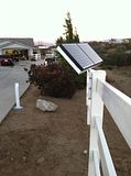 What follows is a synopsis of the design/specification/construction: I used two (2) 1-1/4" Heim joints as hinges, each sandwiched between two (2) 4"x4"x1/4" angle supports. Each Heim has a through welded threaded insert (“bung”) extended with 1/4" wall DOM (drawn-over-mandrel seamless) tubing inside the 5" sq. x 1/4" wall post. The Heims are aircraft grade, are rated at 125K psi shear strength and the bolts are grade-8 USA made, 1" fine thread with grade-8 Nylock nuts from Caterpillar so they "should" hold. The Heims also allow for the driveways cross slope. The latch post and open post assemblies are similar to the hinge post except for only using 4” square tubing rather than a 5” and a 4”. The latch post footing is 30”sq. x 24”D and the open post footing is 18”sq. x 20”D. All posts are filled solid with concrete to increase bending resistance. The solar panels are rated at 10W each. I was getting about 20VDC yesterday at around 4:00PM. I assume that the control board regulates the charging current to the two batteries. Gate dimensions are 17’-7”W x 5’H Steel wall thicknesses: 5” main post is 1/4” 4” main posts are 1/4” 4” gate verticals are 1/8” 2x4 rectangular tubing is .060” ALL flat plate is 1/4” Weights: hinge post = 320#, footing = +/- 9,000# gate = 360# latch post = 115#, footing = +/- 1,900# open post = 40#, footing = +/- 500# solar post = 40#, footing = +/- 100# (steel and concrete inside vinyl fence post) FUTURE brick wrapped concrete block columns = +/- 8,500# / each operator and various brackets = +/- 20# Finish: Rustoleum Industrial primer (enamel) Rustoleum Industrial gloss white (enamel) |
|
quikduk
CTW Life Member
   Dog House
Posts: 552
|
Post by quikduk on Oct 9, 2013 11:13:41 GMT -5
I also discovered that I had a harmonic issue with the gate and operator and decided to tackle the gate harmonic disturbance (in The Force?) this past weekend. I disconnected the gate ram and tried it back and forth. It appeared to make a slight tonal noise which I think was being amplified significantly by the steel tubing it was attached to.
I picked up some high-expanding foam, took all of the bolts out and proceeded to foam the inside of the tube…and make a general mess out of everything as well as glue two of my fingers temporarily together (hole in my nitrile glove)…nice. I still have some nitrile glued to my right thumb that will have to wear off and my fingers are somewhat raw from pouring acetone on them to remove the glue. BTW, California “approved” acetone is CRAP now.
I also pulled the ram partially apart and sprayed some Lucas “Tool Box Buddy” (fine penetrating, non-caustic/non-corrosive oil) into the area around the inner and outer o-ring seals as well as through the access hole in the bottom of the housing. This seems to have quieted the minor ram noise and the foam appears to have done the trick. The Mfr. says silicone but I only use that occasionally on the outside of the ram as it didn’t work well when I sprayed it inside.
I also silenced the operator opening/closing alarms as the beeping was very loud at 0600hrs. I also added some stiff felt padding to the latch post bracket to quiet the gate stopping and latching motion as I had to max out the closing force potentiometer on the operator to counteract the “occasional” winds we get. I may try to readjust the gate closing distance and force later but I need to test it on both a no-wind day and a blustery day to see the best mix.
What is left is to save my pesos for the brick wrapped block columns, electrical doo-dads and the gate logo/brand and gate dog-proofing.
|
|
|
|
Post by affordable on Oct 14, 2013 8:33:28 GMT -5
I also discovered that I had a harmonic issue with the gate and operator and decided to tackle the gate harmonic disturbance (in The Force?) this past weekend. I disconnected the gate ram and tried it back and forth. It appeared to make a slight tonal noise which I think was being amplified significantly by the steel tubing it was attached to. I picked up some high-expanding foam, took all of the bolts out and proceeded to foam the inside of the tube…and make a general mess out of everything as well as glue two of my fingers temporarily together (hole in my nitrile glove)…nice. I still have some nitrile glued to my right thumb that will have to wear off and my fingers are somewhat raw from pouring acetone on them to remove the glue. BTW, California “approved” acetone is CRAP now. I also pulled the ram partially apart and sprayed some Lucas “Tool Box Buddy” (fine penetrating, non-caustic/non-corrosive oil) into the area around the inner and outer o-ring seals as well as through the access hole in the bottom of the housing. This seems to have quieted the minor ram noise and the foam appears to have done the trick. The Mfr. says silicone but I only use that occasionally on the outside of the ram as it didn’t work well when I sprayed it inside. I also silenced the operator opening/closing alarms as the beeping was very loud at 0600hrs. I also added some stiff felt padding to the latch post bracket to quiet the gate stopping and latching motion as I had to max out the closing force potentiometer on the operator to counteract the “occasional” winds we get. I may try to readjust the gate closing distance and force later but I need to test it on both a no-wind day and a blustery day to see the best mix. What is left is to save my pesos for the brick wrapped block columns, electrical doo-dads and the gate logo/brand and gate dog-proofing. Look at the large white plug in, that connects the instrument panel, on the end of the plug in there is a large Red or a Large White wire, make sure that wire is making a good connection. Since the 1- piece instrument panel does have the amp meter working, it could be a bad board in it which is not repairable, you would have to replace the panel Tommy Affordable Tractor Sales "Your Jinma Parts Superstore" www.affordabletractorsalesco.com |
|