3RRL
Administrator  Huge Kama
Posts: 2,027 
|
Post by 3RRL on Oct 17, 2009 23:03:05 GMT -5
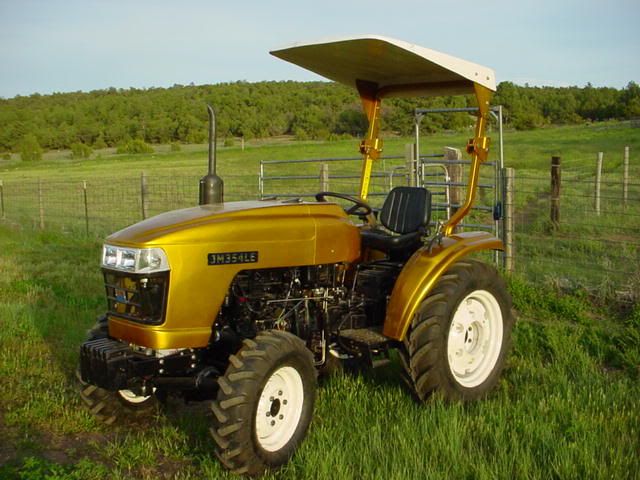
To make a long story short, I busted the 4wd on Loretta's 284. Ever since reading about how careful to be ... not using 4wd when using the loader for example, we have been using it sparingly and only when needed. Well, when I was using her 284 to rip trenches for the sprinkler systems, I needed to use 4wd to pull through the hard Earth. I heard (and felt) that the 4wd was no longer working properly. But it was strange ... It felt like it wanted to spin the fronts and did at times, but then it would slip making a "click click click" noise. It seemed like the 4wd was still working except under heavy load. That's when it would "click" over and the fronts would not spin (no 4wd) at that time. Anyway, there have been several threads about 4wd not working so I read up on them and the other links. It seemed that many of them had to do with the 6 steel balls at each end of the front drive shaft perhaps coming out of there position. But there were also some where the front axle broke. So the first thing I did was jack up the tractor (all 4 wheels off the ground). Then I started turning the front tires. The front drives seemed to be OK and so did the front differential. There was no grinding noise whatsoever and when I turned one front, the other tire turned in the opposite direction. I jerked them back and forth quickly to see if anything sounded broke in there, but it all seemed good. I removed the cover to the transfer case and physically checked to see it the gears were good. I also checked to see if the lever was moving the engaging gear from 2wd to 4wd and that was OK too. Then I started to remove the front drive shaft. After removing the cross brace on the bottom that covers up part of the drive shaft, I removed the hose clamps and slid the cover back to expose the front engagement. I removed the snap ring (which was good) and saw that the 6 steel balls were all in there behind the star shaped washer. I did the same to the rear engagement and looked at it too and it seemed just fine. I decided to lower the fronts only and leave the rears jacked up but on a rolling floor jack. I carefully started the tractor, put it reverse and gently let the clutch out. Well, the tractor moved ... the fronts were engaging alright!! I did it in forward and same thing. So the 4wd did work under light load but slipped under heavy load. At that point I was pretty perplexed and decided to call Tommy at Affordable Tractor for his advice. He explained several possibilities and told me I should have completely removed the front drive shaft. Dang, I knew I should have done that and not just "eyeballed" the joints. After explaining to him what the tractor was doing, I asked if it was possible for the balls to wear a groove in the splines so they had to "jump over" the splines? Because that is what it seemed like it was doing ... that thought was going through my mind when the tractor was acting like I described. He said it was possible. In any case, he said he had all the parts I would need no matter what. So I jacked the tractor back up and removed the front drive shaft. First photo shows the front engagement which I left on the tractor because it was so clean and perfect. Second photo shows the front part of the drive shaft with the grooves for the balls. The snap ring and star washer (ball keeper) were in great shape too. Oh, and my chickens were keeping company while working... Rob- 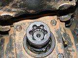 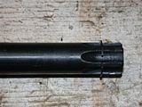 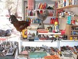 |
|
3RRL
Administrator  Huge Kama
Posts: 2,027 
|
Post by 3RRL on Oct 17, 2009 23:24:53 GMT -5
Then I removed the rear drive shaft engagement housing right at the transfer case. Once I removed the drive shaft and coupling, the transfer case shaft was exposed. And indeed, the 6 balls had worn a groove into the shaft. It was exactly like I had pictured in my mind. The balls were turning the front drive shaft under light load, but under heavy load they would "jump over" the splines...no 4wd at that point. There was a broken snap ring but no snap ring groove on the shaft. In the close up of the "coupler" which is the part that houses the balls, you can see that the front of it is bell mouthed and worn. I mic'ed the balls and they were still round (sort of) ... 8mm or around .3149". The tubular dowel behind the spring was OK too. 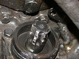 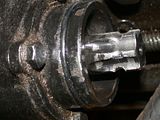 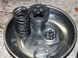 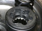 Next was to remove the shaft from the transfer case so I could fix it. Tommy told me to tap it forward and it should come out ... which it did. These photos below are of the parts diagram in the manual and the actual "gear and shaft" inside that little transfer case (parts #19 and #24). The manual calls that housing which projects down the "transfer case". Last photos shows the good spline on the front coupling and the ruined spline from the transfer case. Rob- 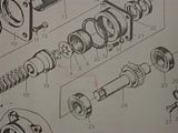 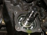 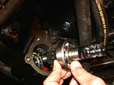 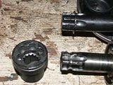 |
|
3RRL
Administrator  Huge Kama
Posts: 2,027 
|
Post by 3RRL on Oct 17, 2009 23:37:35 GMT -5
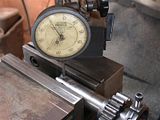
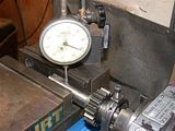
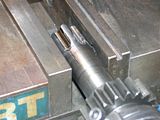
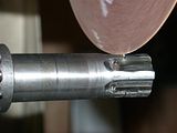
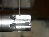
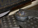
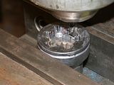
I checked the shaft for hardness and a file skipped across it, so it was plenty hard. My plan was to weld up the grooves and also the sides of the shaft. I would do the same to the housing part. Then I would re-cut the grooves on the shaft and inside the housing. After doing some math, I came upon what clearances they (the Chinese) had in there. It was like .040" per side and I thought that was too much. Also, there was more engagement from the balls to the housing than to the shaft, so I decided to make it about equal in each part. I had to put my Miller 330 APB TIG elder together to do this welding. You can see it between the surface grinder and one of my milling machines. Once I got it set up, I welded both the outer housing and the shaft up. I used H-13 tool steel rod so it would be plenty strong and hard. 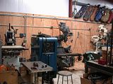  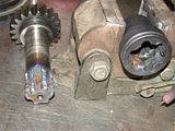 When I finished welding the parts, I turned them on my lathe. On the shaft, I had to use the same diameter as it was because there is a bearing which slips over that end. I was going to make it larger to lessen the clearance between the two, but duh... On the housing, I welded enough to make only .020" per side clearance from shaft to housing. This cut the original clearance in half. Rob- 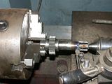 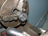 |
|
3RRL
Administrator  Huge Kama
Posts: 2,027 
|
Post by 3RRL on Oct 17, 2009 23:56:13 GMT -5
|
|
3RRL
Administrator  Huge Kama
Posts: 2,027 
|
Post by 3RRL on Oct 18, 2009 0:13:37 GMT -5
Getting to the end of the repair now ... I realize that CV joints use ball bearings and most of that is because the joint not only has to mate to transfer power, but it also has to swivel. In this case, once the joint has been made via the balls, there really is no swiveling. With that in mind, I decided to use 5/16" hardened dowel pins (.313 dia) and cut them about .400" long. What does that do? Well, instead of having one contact point around the equator of the ball, I now have a cylinder making contact up and down the entire groove. So I cut off some dowel pins I had and fit them into the grooves between the shaft and housing. They fit perfectly with very little clearance...at least a lot less than what was stock. And there should be no "jumping" over the splines anymore. 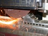 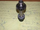 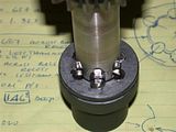 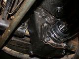 I knew re-assembly would be harder than with the balls, but once I got everything lined up like on the bench, the whole shebang went together and fit like a glove. After filling the trans fluid back up, I immediately tried it out. Man, the 4wd was smooth as can be with no clicking or anything. There is still enough clearance for everything to be assembled and work correctly. But I feel it's an improvement over the stock set up. I say this because on my Kama, the front drive shaft has a multi-splined coupler that slides (fits perfectly) from one spline on one shaft to the other. So I feel making the Jinma connection closer to that of the Kama (by using dowel pins instead of the balls) will be an improvement. Rob- 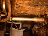 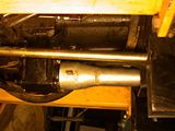 |
|
|
|
Post by Rich Waugh on Oct 18, 2009 19:37:37 GMT -5
Well Rob, you're up to your usual standards of performance - break the thing and then fix it better than new. I'm thinking I should fly you down here to break my tractor and fix it so I'd have a blueprinted tractor, too. (grin)
Really excellent work on that repair and upgrade to the CV joint. I guess it really isn't a true CV joint, just an ersatz one to facilitate assembly. Your substitution of the dowels for the balls makes a lot of sense and should make a far stronger coupling. I'm going to remember that concept and maybe use it someday.
Did you switch out the balls at the other end, too? Seems like they will now be the weak link in the chain if you don't put dowels in there as well. Probably could do that without re-machining it, just swap out the ball for dowels. In fact, that seems like a good idea for anyone to do if they have the "loose balls" syndrome.
I spent the day bushhogging in the mango orchard today. We've had a bunch of rain lately and the damn guinea grass was as high as the canopy on the tractor! Made driving around a bit too exciting, but no problems-so far, anyway.
I did run into one problem, but I'll start a separate thread on that.
Excellent work once again, Rob - you da man!
Rich
|
|
carld
CTW Member

Posts: 81
|
Post by carld on Oct 18, 2009 20:42:33 GMT -5
 hmm, I use my 254 a lot in 4 wd and have thought a lot about the little balls driving the load. I had some trouble with the balls jumping out because the snap ring groove was not deep enough. I suppose I should pull my drive shaft and see what it looks like now since I have about 750 hrs on it. Rob, how many hours are on her 284?
|
|
|
|
Post by bradblazer on Oct 18, 2009 21:17:33 GMT -5
Hey Rob,
Great work as usual and good thinking on the dowel pins. I'm with Rich wondering if you thought about putting them in on the other end too.
Ha ha I was making bets with myself as I started reading whether you would order new parts or fix them. Super work all the way around. Better than new!
Thanks for yet another super informative post!
Brad
|
|
3RRL
Administrator  Huge Kama
Posts: 2,027 
|
Post by 3RRL on Oct 22, 2009 20:17:22 GMT -5
Hi guys, Thanks for the great compliments. Loretta only had 185 hours on it when this happened. Waaay to soon for that to happen. At first I thought the shaft was soft, but no, it was hardened. After talking to Tommy, I seriously thought about buying replacement parts. But I also felt I could probably weld it with tool steel and re=machine it pretty quickly. That's when I made the decision to make the new cuts sized for the dowels I had. After all, they were within .002" of the Metric balls. To my shame, I did not change the fronts over to the dowels. I suppose I should but man, I've been working like dawg at my part time job down South. You guys are right about doing that though, it would not take long to do. The only thing that was a pain was to remove that bracket/ fel tower brace that runs along the bottom of the motor and covers up the rubber boot around the drive shaft. It's got 8 small bolts holding it on to the fel tower and 4 big bolts to the engine casting on the underneath. When I first looked under there, those 4 big bolts (uses a 24mm socket) were not installed. None of the holes lined up to the engine casting. I used an endmill to elongate the holes so they would line up. But they are no sweat to install or remove. It's those 8 smaller bolts that are a pain. On 4 of them you can get a socket on because of no room. The other 4 you have to use a pry bar to move the steel hydraulic lines that cove the heads. Once that bracket is off it's really easy to remove the drive shaft though. So yeah, maybe later I will install the dowel pins in the front of it. ;D BTW, I could make that entire shaft and gear from scratch if I really wanted. I I am so lucky to have all the tooling to cut and grind gears and such. In fact, my project down South just required 20 unwinding cores for the mold I am building (design and build). The gears on those cores are also solid. Here are a couple pictures after I finished grinding the OD. The only I did not do myself is grind the modified Acme thread on the tips because they have .018"/inch shrinkage in their pitch. I sent that out to a thread grinder. But all the rest before and after heat treat I did myself. Also a shot of where the cores fit into another insert (stripper insert) and an excellerated cam for part ejection which moves an entire mold plate forward. Sorry for boasting like that, but really, that shaft with the gear on it would be a piece of cake to make. Thanks again guys, Rob-   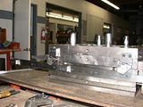 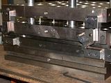 |
|
|
|
Post by affordable on Oct 22, 2009 20:24:15 GMT -5
Rob,I have 84 of those shafts on the shelf,so don't start making them yet I need to sell a few first.  Great job on getting it fixed,job well done !!!!!! Tommy Affordable Tractor Sales www.affordabletractorsalesco.com |
|
3RRL
Administrator  Huge Kama
Posts: 2,027 
|
Post by 3RRL on Oct 23, 2009 16:22:11 GMT -5
Rob,I have 84 of those shafts on the shelf,so don't start making them yet I need to sell a few first.  Great job on getting it fixed,job well done !!!!!! Tommy Affordable Tractor Sales www.affordabletractorsalesco.comHey Tommy, Thanks for all the help you gave me over the phone! Especially in taking that rear shaft out of the "transfer case". It freaked me out when I tapped it until the rear bearing hit the other gear on top of the shaft. It felt like I hit a solid obstacle. After talking to you, I tapped it a little harder and she came out. The rear bearing stayed in the transfer case housing. You know, I really thought about ordering all the components from you but decided to give "the repair" a try first...I had all day to do it. Plus, if I screwed it up even worse I knew I could call you for new parts. I know your parts would be a lot less than having to make an entire new shaft (lots of work), but the repair I did was a lot less work than making the entire shaft new. (LOL, I didn't want to let Brad down either hahaha) Thanks again! Rob- |
|
GuglioLS
Administrator  Jinma354 LE
Posts: 1,276
|
Post by GuglioLS on Oct 25, 2009 10:15:55 GMT -5
Super repair job Rob!
I'm impressed by your replacing ball bearings with dowel pins, what a clever idea that was. Your always thinking outside the box. What you come up with for fixes never cease to amaze me. Thanks for the great pics and procedure, now I must go check my drive shaft to see if I can remove the ball bearings and replace with pins, seems like that really is a superior way to do it. No way could I micro weld and machine a fix like that!
OAN - I see your shop and all your machines are fully up and operational, I bet your glad thats done. Oh and the chickens running amuck in the shop, HaHaHa that's a hoot, so I guess they outgrew the portable chicken coup? You and Loretta sure are running a regular Green Acres up there in Three Rivers ;D
Oh the new mold is impressive, what's it weigh? and what's it going to make? Those things are like magic. I suppose not too many have a real appreciation for what it really takes to make a precision mold that produces plastic parts. It's mind boggling to me.
Larry
|
|
3RRL
Administrator  Huge Kama
Posts: 2,027 
|
Post by 3RRL on Oct 25, 2009 13:46:31 GMT -5
Hi Larry, Thanks for the compliments man! When I saw what those ball bearings had done, and what their real function was (in this case), I was just thinking "Now what would Larry do here?" So I came up with the thought that all they do (the ball bearings) is transfer the power to the other shaft. And using longer "transfer" components seemed like it would be a much better condition ... much like the fully splined shaft on my Kama front drive shaft. If you are thinking about changing the balls out to dowels, you can probably get 8mm dowels. At least that was the size in Loretta's 284. I used 3/16" (Ø.313") dowels because I had them already. I think they would work in the stock shaft and housing slots/flutes/splines whatever you call them. I had some balls that were worn down to Ø.314 anyway. The key is making them as long as you can so they fit into the existing splines and are covered up by that star washer and held in place by the snap ring. I used .400 length, but I think a little longer would still fit? I should have experimented to see what the actual length would be and still go in there. Nevertheless, I really feel it's an improvement over the OEM design. Thanks again!  Yeah, I got the shop in the barn set up better and better each time I have to do something. Glad you noticed. The chickens are doing really good. We let them free range every day. Big Red protected his chickens from a Coyote attack (Coco was in the house) one morning but the coyote only got a mouth full of feathers luckily. Now I sit outside with one of my rifles for a while when I first let them out of the coop. I make sure Coco is out too. She and the chickens are sort of pals now. Hey, how did Katherine's and Robert's wedding go? Did you get our card? I'll bet it was a big day for you and them. But at the same time, I'll bet you and Esther are glad it's over. ;D Take care, Rob- |
|
gears
CTW Member

Posts: 3 
|
Post by gears on Oct 19, 2013 15:24:25 GMT -5
I have a Jinma 284 and also stripped the splines on the shaft where the front balls make contact in the housing. Too much front end loader abuse lol. I used Rob's ideas and switched the balls over to dowels on both ends of the shaft to strengthen the unit better then OEM. I purchased a new shaft, and housing from a dealer to replace the damaged ones. No extra machine shop work was required to switch the stock housing and shaft over to dowels from balls. I bought 8mm x 25mm hardened steel dowels from Fastenal (Part #0154393) and cut them in half length-wise using a cut off blade in my angle grinder. That gave me two 12mm dowels out of each long single one. I wasn't able to find anyone selling 8mm x 9mm long dowels. I then used my bench grinder to shorten each half section of the 12mm dowel to 9mm in length. Because each of the dowels were chamfered slightly on each end originally, I found that 9mm was the longest length to make them and still get them to fit. I placed the chamfered end into the housing, and placed the square cut off end against the washer/C-clip. Using axle grease to hold the dowels into position, I reassembled the shaft into the housing. It'll be interesting to see how much stronger the 4 wheel drive will be now. Picture shows the dowels ready for install, and the new shaft beside my damaged one. Attachments:

|
|
gears
CTW Member

Posts: 3 
|
Post by gears on Oct 19, 2013 15:26:11 GMT -5
Couple of more pictures showing the axle with the new dowels ready to be re installed in the tractor. Attachments:

|
|






 hmm, I use my 254 a lot in 4 wd and have thought a lot about the little balls driving the load. I had some trouble with the balls jumping out because the snap ring groove was not deep enough.


