3RRL
Administrator  Huge Kama
Posts: 2,027 
|
Post by 3RRL on Feb 6, 2008 12:56:06 GMT -5
I finally got enough time to start a thread and upload some pictures of my latest project, adding hydraulic side links to my bitchen Kama 554. I got quite a lesson about hydraulics in my last project so I thought to start this one now. Couple of things I wanted to accomplish were to have beefy hydraulic cylinders to take the place of the cheesy turnbuckles and also to mount double pilot operated check valves on them to prevent any leak down. This is important to me because I use my side links to "cinch" up the backhoe sub frame assembly and it needs to be that way. One other thing was to standardize the hitch pins to Ø1" on both the tractor upper lift arms and lower drag links. This photo is some, not all of the components for the project. My hoses and the rest of the adapters are still on order. 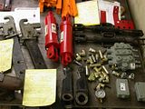 |
|
3RRL
Administrator  Huge Kama
Posts: 2,027 
|
Post by 3RRL on Feb 6, 2008 12:58:30 GMT -5
I measured the Kama to be certain I'd have enough clearance to get big Chief cylinders and those giant check valves at Surplus Center. I can't wait to try them out. The cylinders are Ø3-1/2" with a Ø1-3/4" shaft and 8" stroke. That should be plenty heavy duty enough to keep from bending, unlike the Ø1' turnbuckle shafts. I measured the travel of the existing turnbuckles and it was 7-1/2" so I'll have to modify the Chief cylinders a little to alter the stroke. I wanted 2 cylinders because I have a dirt road that requires a lot of maintenance and I'm constantly adjusting those side links for crowning the road or cutting gutters, etc. I also use the box blade quite a bit in reverse as a bulldozer blade so this way I'll have a 4 way blade almost like their 6 way blades. Using the box blade in this manner requires heavy duty drag links, stabilizers and side links, or something will bend. I'm going to attempt to hard-plumb the DPOCV to the cylinders myself. Then also add a Prince 3 spool valve with power beyond. I'm planning to use the new valve to operate the side links and the hydraulic and top link cylinder. Then I'll use the existing rear remote valve to operate the hydraulic box blade with one spare set remotes....maybe...I'm not 100% certain yet. Anyway, the first thing I ran into was that the new cylinders have a 1-1/8" width between the clevis and my upper lift arms have swivel balls that are 1-3/8 thick. So I had to grind them down to give me some clearance. I did that on the surface grinder in my garage shop. Also a picture that shows the difference between the two. Now they fit in between the new cylinder clevis. 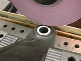 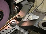 |
|
3RRL
Administrator  Huge Kama
Posts: 2,027 
|
Post by 3RRL on Feb 6, 2008 13:00:06 GMT -5
Next I had to bore open the swivel ball from Ø7/8 to Ø1" and also do the same on the drag links to accept the larger pins. Now all the pins and holes are the same and I can switch them around instead of having all kinds of different sizes to mess with. It rarely happens that everything you are wanting to do fits perfectly...sometimes not at all. So all these little machining operations add up or the stuff will not work. 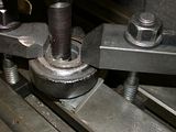 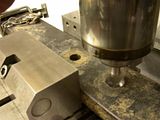 |
|
3RRL
Administrator  Huge Kama
Posts: 2,027 
|
Post by 3RRL on Feb 6, 2008 13:04:26 GMT -5
I finally got the bores to be just right... You can see the good one on the left vs the sloppy one on the right. I also had to mill some clearance onto the upper lift bars to allow enough pivot room for the larger hydraulic cylinders. You can see the cut out in the first photo leaving a thick section strong enough to lift the tractor up. Then I had to make a couple of brackets to accept the additional rear remotes and also for the new valve. So I welded some pieces I had lying around and drilled a bunch of holes in them. I made the rear remote bracket so I can bolt it onto the rear fender. This will put it more out of the way of the PTO and lift links making it safer and WAY more accessible. 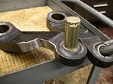 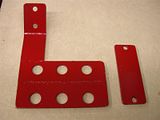 |
|
3RRL
Administrator  Huge Kama
Posts: 2,027 
|
Post by 3RRL on Feb 6, 2008 13:07:46 GMT -5
When I pinned the new cylinders onto the top lift arms they now worked great. But the the clevis on the bottom links needed to be cleared more to allow pivoting for the drag link (lower lift arm). So back to the milling machine and started to whack away the interfering portions. I ended up with over an inch of usable thread engagement so I thought that was plenty good. I looked it up to be sure and found that a 1-1/4-12 UNF thread holds 15,000 pounds at 1-7/8" engagement, so the 1'' should give me just about half that per thread....giving the 15,000 between the 2 of them. My tractor will never pick up anything over 3,500 lbs on the 3pt.... 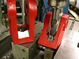 OK, so now the clevis is finished machined but when I screwed it back onto the rod, the thread was sticking out about 3/4 inch...that won't work! I filed the threads and determined they were "soft" and I could probably cut them off. So into the saw to cut off the excess. 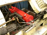 |
|
3RRL
Administrator  Huge Kama
Posts: 2,027 
|
Post by 3RRL on Feb 6, 2008 13:22:39 GMT -5
Finally I screwed the clevis's back onto the cylinders and the are ready to paint and install. You can also see the Prince 3 spool valve I'm using for the new remotes, since I'll be using the existing remote valve that came on the tractor to operate the side links. After that, it's outside the garage for a couple of coats of the primer paint. Then I'll put the final coats on and take everything up to the property to mount to the tractor. 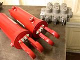 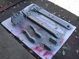 Hopefully the rest of my couplers and the hydraulic hoses will arrive via UPS next week. I'm planning on spending Labor Day on the property with all my kids and grandkids. We will all be camping there. With that in mind, I may not have time to do the assembly anyway. I figure I might need a full day to run all the plumbing and bolt everything together. Again, if I forget something, it's at least a 4 hour loss by the time I get back from the nearest town with a hydraulic store in it. Also, I might need some extra adjustments??? |
|
3RRL
Administrator  Huge Kama
Posts: 2,027 
|
Post by 3RRL on Feb 6, 2008 13:27:02 GMT -5
I went up to the property for Labor day and was having the kids and grandkids up for a giant camp out. It sure was a lot of fun to have most of them up there. I didn't think I'd have time to do any work on the tractor, but Loretta took Friday off so we left Thursday night, giving me a little time to work on the side links after all. I brought up many swivel connectors to be sure I could do the job. I needed them because I was not sure how it was going to turn out. Especially mounting...hard plumbing the double pilot operated check valves I bought from Surplus Center. I had machined some various nipple lengths in order to get the spacing correct for the hard plumbing. Here's some fittings and stuff I brought up. 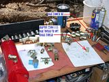 |
|
3RRL
Administrator  Huge Kama
Posts: 2,027 
|
Post by 3RRL on Feb 6, 2008 13:29:56 GMT -5
After trying it several times, I finally got the right combination and made a good plumbing job of it. I used pipe joint compound for the NPT fittings. The others were SAE and JIC fittings. Here's what the cylinder looks like with the check valve mounted. It was a lot harder than I thought but came out just fine. One thing for sure, the Surplus Center DPOCV is a lot bigger than the CCM one on my top link cylinder. 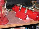 Then I took the cylinder assembly and mounted it to the tractor. I had previously re-attached the top lift arms and lower drag links to be certain I had them in the correct position. The top lift arms are splined so you can set on the tractor at different positions. So I had to check the full movement of the arms to see if there would be any binding or interference. I also checked the to see where the full length and shortened length of the cylinder would position the lower drag arms. Anyway, this is how the cylinder looks when in position. 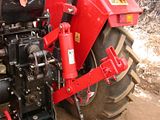 |
|
3RRL
Administrator  Huge Kama
Posts: 2,027 
|
Post by 3RRL on Feb 6, 2008 13:32:58 GMT -5
When considering how to plumb the tractor, I had decided earlier on that I would use the new 3 spool valve to control the top link and also the hydraulic rippers on my box blade. It will also give me one more set of remotes for whatever else I come up with? That meant making a new Quick dis-connect bulk head bracket and having all the hoses go there. Unfortunately, I didn't have time to install the new valve. We were planning on dove hunting and also going up to Sequoia to see the giant Redwoods. Another thing I had to do was trench some deep holes for the solar guy. They are for the solar trackers and had to be 4' x 4' x 5' deep!!. So I hooked up the new side cylinders to the old valve that ran the rear remotes. In fact, it made good sense since it's levers were next to each other, left and right. So it was easy to tell which lever runs which. That way the 3pt system was in tact and ready to use. I also got some metric adapters (22mm x 1.5 pitch) to make the connections to the Chinese threads. 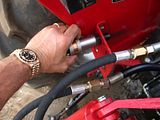 After getting everything screwed together and trying them out, I had to be certain none of the hose interfered with the 3pt system and that they had enough room and play regardless of what I hooked up...including the PTO pump for the backhoe. So this is what that turned out like. No leaks and everything fits, works and is tucked away nicely. To my surprise, even the big check valves look decent. Right after that, I hooked up the backhoe and dug those big holes. Next time up I'll tackle the 3 spool valve installation. 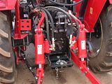 |
|
3RRL
Administrator  Huge Kama
Posts: 2,027 
|
Post by 3RRL on Feb 6, 2008 13:35:01 GMT -5
I would highly recommend this mod to your tractor if not done so already along with the hydraulic top link. The capability to equalize, tilt, adjust easily is so much useful in many applications. It's all done with a great viewpoint from the tractor seat. The best part is grading for example, you can drag your box blade with infinite settings WHILE MOVING and instantly see the result of the grade of cut you are making.
There have been many, many times I've had to stop the tractor, park brake (maybe turn engine off), get off and adjust the turnbuckles on the side and top links. Then climb back on (maybe start) park brake off, put back in gear and drive ONLY to find that my adjustment was not adequate...then do it over again until I got the right setting to produce the desired finish or grade. Of course, that changes after moving forward a bit and guess what? So now this whole thing is done from the operators seat and adjustable for varying conditions.
Once I get the road smoothed constant, crowned and guttered the way I want, the check valves will earn their keep.
The cylinders I chose were expensive and I bought a lot of fittings. The hose from Agri Supply were 1/2" and relatively inexpensive. I ordered everything on line after getting the right lengths and figuring out what connections I needed. The check valves were expensive too, but worth it for me. The way I did it and the cylinder size/quality I chose ... it cost me around $650.
I figure if a guy wanted to do this project he could get smaller cylinders and less expensive ones...they will all work as long as they fit and allow enough clearance in the system. Without the check valves you can do it for about $400 including a 2 spool lever valve. This is for 2 cylinders...if you use one it is even less expensive by the reduced cost of the valve, cylinder, fittings and hoses.
Another way to consider doing it is to use your rear remotes as the power supply with quick disconnects to the cylinder(s) AND a check valve. Theoretically, a guy could use the QD's to set the desired tilt etc. and remove the QD's to run another implement. The check valve should hold the cylinder in that position until you move it. If you use only one cylinder and you have 2 rear remotes, you could leave it hooked up all the time and maybe not even need the check valve? then you can do it for the cost of 1 cylinder, fittings and 2 hoses...no spool or check valve.
Rob-
|
|
3RRL
Administrator  Huge Kama
Posts: 2,027 
|
Post by 3RRL on Feb 6, 2008 13:39:16 GMT -5
Last weekend I got enough time to install the new 3 spool valve and plumb up all the hydraulics. There is a lot to making the hose connections come out the right length and using the right fitting connections. Also in picking the path so they don't interfere with getting around the cab. I used a garden hose to simulate hydraulic hose to measure lengths needed. Before going in to that, I had been asked to show the available tilt on the new cylinders. There was a question about the possibility of the drag links (lower arms) twisting from side to side and causing an interference with the cylinder yokes. I tilted them up and down to full extension and then stuck a 3/4" pipe through the hooks of Pat's EZ lift system. There was enough room but a little tight. However, I'll probably never have this drastic of a difference between the 2 cylinders? (maybe). If you look closely, you can see the raised arm on the left actually has some tilt to wards the right one, and visa-versa. I also removed the stock quick disconnect bulkhead bracket on the left side to give lots of room behind the tractor. If you look closely on the right of the photo, you can see where I ran the power beyond and return to sump along the inside of the right rear fender. 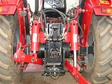 |
|
3RRL
Administrator  Huge Kama
Posts: 2,027 
|
Post by 3RRL on Feb 6, 2008 13:44:24 GMT -5
I bought a Prince 3 spool open center valve with power beyond to control the new rear remotes. I now have 3 sets of rear remotes with this valve. Remember that the existing 2 spool valve (was for my rear remotes) now controls the hydraulic tilt cylinders individually. The valve is very big and I had to pick the right place to mount it so the control levers were within easy reach when I was looking back wards. I also mounted the levers facing inwards so they are really easy to get at. I ended up installing it into a tool box I made and mounted on the right fender. I cut the box to fit the entering and exiting hoses and made a steel bracket to support it. It looks a little busy but it is completely out of the way. I managed to route 6 hoses between the ROPS and the tool box. The power in, power beyond and return to sump all follow the ROPS down to the floor board. I used 4000 psi hose bought from Agri-Supply. Not too bad for having nine ½" hoses altogether. Here are views from the front like from the steering wheel, showing a corner of the the drivers seat on the right. And one from the rear ward position, showing a corner of the driver's seat on the left. I can still keep 2 grab chains and some tools in the rest of that tool box. 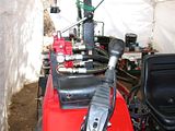 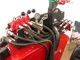 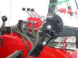 |
|
3RRL
Administrator  Huge Kama
Posts: 2,027 
|
Post by 3RRL on Feb 6, 2008 13:54:12 GMT -5
This is a view from the rear of the tractor to show where the rear remotes are now located. I put them higher up on the back of the right rear fender. Look how easy they are to get now, compared to the old location which was blocked off when you had an implement mounted. The new location is much more user friendly and all my attachment hoses still reach to the new location. The rest of the cylinder plumbing also looks good. 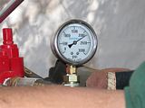 These last couple photos are close-ups. This one shows the 3 new sets of remotes on the Kama. And finally, after checking everything for leaks (one fitting I forgot to tighten) I had Loretta take a shot of the new pressure gauge showing the system at 2300 psi when under full load. That's where my valve's reliefs are set for safety. My main hydraulic system is rated to operate just under 2500 psi. 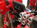 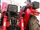 |
|
3RRL
Administrator  Huge Kama
Posts: 2,027 
|
Post by 3RRL on Feb 6, 2008 13:55:36 GMT -5
It was great to see how the pressure ran up when using the loader and other implements and then spiked up to the relief valve pressure under full load. I was really surprised how little pressure the loader, 3pt and other cylinders handled most loads, only spiking when I maxed out at the end of the travel. Now I can keep tabs on how the hydraulic system is working and whether it starts to show excess pressure due to a dirty strainer or blockage, or when there is no pressure and a possible leak.
I hope this project may have helped someone who is considering hydraulic additions. There might be improvements whereby you can improve your installation....learn from my mistakes? My recommendation is to use either JIC fittings or SAE fittings where possible. They are very leak proof and run up to a positive stop and an "O" ring. The NPT fittings are more difficult and require pipe dope to get a good seal. In my case, there were several places I had to go from Metric 22mm x 1.5mm pitch (not BSP) to American. This made for an interesting collection of fittings I needed.
I've tried to show what is involved and that even a hack like me can make the installation with success. Everything works and I am very happy with the results.
Rob-
|
|
3RRL
Administrator  Huge Kama
Posts: 2,027 
|
Post by 3RRL on Feb 6, 2008 14:00:17 GMT -5
I will also be pushing in a new road that will run from the existing road toward the West property line and then South. Then back East to my camp. It will open up another part of my property that is pretty secluded at this time. I figure to cross one pretty good arroyo and will be using the box blade pushing backwards like a bull dozer. I will be able to control the slant of the road easily using my new tilt cylinders I know there was some concern about the clearance of the clevis ends on the hydraulic cylinders when severely tilted. I realized I had not posted any photos of the box blade mounted but only with the lower arms extended and retracted. This weekend I was able to take a few pictures so you could see the amount of tilt I can get on the box blade and no binding in the clevis mounts. 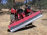 . |
|