GuglioLS
Administrator  Jinma354 LE
Posts: 1,276
|
Post by GuglioLS on Sept 15, 2008 21:57:19 GMT -5
Hi Brad, Little progress is better than no progress. A word of caution about fittingsandadapters.com/ - there web site looks good with quite a few hard to find fittings. I've never had much luck with them. I tried to order from them several times in the past and never got a thing, left several voice mails and e-mails never got a response. They never answer their phone, maybe things are better with them now? I would try and call first to see if they are still in business. Have you tried: www.discounthydraulichose.com/product_p/6902.htmpart# 6902-10-06 Larry |
|
|
|
Post by bradblazer on Sept 15, 2008 21:58:21 GMT -5
I also shortened the extended rods on the 2 hydraulic cylinders I got for the stabilizers. I didn't want to ruin the blade on my big band saw so I used the hand-held. I started out by marking the cut circle with a wrapped sheet of paper and extra fine sharpie. 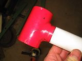  The band saw wouldn't touch the hard chrome so I used an air cutoff tool to cut a groove all the way around the circle.  The hard rubber jaw caps that came with my vise work good for this. 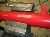 The cut ends came out pretty good.  I beveled the edges and used a bent piece of welding rod as a spacer. The space helps prevent a sharp notch at the root.  Set the SA200 on about 140 amps (DC). I decided to try out the 1/8" 7018AC rods that came in a variety pack in a screw top plastic rod can. Did a test weld to check the settings and then had at the rod end.  This is a good angle on an otherwise not too purdy weld. It's tough to make it look good with a series of short welds on a relatively small diameter. 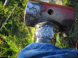 Here's the second cylinder. This time I used 3/32 6011 for the root pass. It made a smaller weld and should be tougher in the notch. The rest is still 7018. That blue thing is an old WET T-SHIRT. (I have no idea what is up with that font.  ) 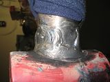 All for now, Brad |
|
|
|
Post by bradblazer on Sept 15, 2008 22:14:12 GMT -5
Larry,
Thanks for the warning and link!
See - there is a little more progress!
I keep flopping around on the sub frame design. nothing real elegant is popping out at me. I have a couple of nice 2x4x1/4 x 71" rectangular rails - maybe it will be best to just stick with a 2-rail design connected way forward by the loader towers. Let the rails take almost all of the torque. I did a calculation with the 2.5" main boom cylinder 14.5" from the boom pivot. 12,300 lbf becomes 178,000 in-lbs of torque. Divided between the 2 rails the stress is 39,700psi vs a 46,000psi yield strength. That's not enough margin for shock loads but I can beef them up from the axle back.
Simple and removable.
Brad
|
|
GuglioLS
Administrator  Jinma354 LE
Posts: 1,276
|
Post by GuglioLS on Sept 17, 2008 0:46:07 GMT -5
Funny I posted within seconds of your real progress reports. Don't you just love cutting through hardened and chromed cylinder rods? I've done a few. On my first try, not knowing any better, bone head me tried it on my band saw, all it did was get more polished. Did you use that portable band saw I see on the floor after grinding through the hardened surface?
Your cylinder rod welds looks great, you should give yourself more credit because what you did is very difficult to say the least.
178,000 in-lbs of torque? yikes! I'm sure you'll come up with something brilliant that will tame the power from that giant BH.
Larry
|
|
|
|
Post by bradblazer on Sept 18, 2008 13:00:15 GMT -5
Thanks Larry.
Yes, I used my Homier $50 portable band saw. It is about the same as the HF one except for the color of the plastic. I used a bi-metal blade.
178,000 might be misleading - that's only 15,000 ft-lbs. ;-) I did use 2500psi to be conservative for hydraulic pressure. The deal with that is that when you let go of the valve, flow shuts off and there is no relief so no telling what the pressure spikes at when you are lowering and suddenly shut the valve.
There is a hydraulic shop in Lenoir that says they have those fittings so I'll run by there Saturday AM and pick them up.
Brad
|
|
|
|
Post by bradblazer on Oct 9, 2008 20:38:26 GMT -5
Here is one of the 2 x 4 tube pieces I will use for the sub frame. It was a machine base and those 1.5" thick solid pads are now gone. I cut the welds with an air cutoff tool and then filled in any cut marks and ground them smooth.   Here it is under the tractor for a test fit. 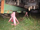 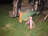 The grey pvc shows where I'll add a 2x2 tube brace for the top link crossbar. There's a quick hitch mounted. I will not incorporate the QH but the rear of the frame will resemble it.  Here's where the front ends up at the base of the loader frame. 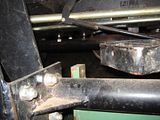 |
|
|
|
Post by bradblazer on Oct 9, 2008 21:27:03 GMT -5
Under the right side the cable operated loader valve is in the path of where I want the rail. It is mounted on a bracket on the loader subframe and I never liked how low it was with that hose elbow sticking down. Originally the power beyond from the remotes was hard piped to the 3ph. When the loader was added, the ran hoses from the remote power beyond to the loader valve and from the loader power beyond under the belly to the end of that hard pipe. I will shorten the hard pipe to eliminate the 2 extra trips under the belly and add a set of quick connects to allow the backhoe to be connected in series. 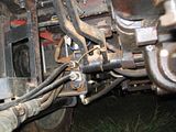 |
|
|
|
Post by bradblazer on Oct 9, 2008 21:38:57 GMT -5
I cut off the flat part of the plate where the valve mounted and welded a piece of angle iron to the front edge to act as a standoff. With the valve rotated 90 deg. the bracked mounts to 2 existing holes in the cast iron floorboard. 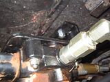 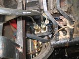 Here you can see how high it now is relative to the loader subframe. 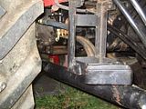 |
|
|
|
Post by bradblazer on Oct 9, 2008 22:12:39 GMT -5
Here is the shortened pipe with quick connect going to the 3ph supply. Originally I was going to re-braze the round end for the 22mm compression fitting but with all of the adapters it put the quick connect into the floor board. So I just drilled out a 1/2" nptf adapter and slipped it over the pipe and welded it on. Note the vestigal nut  . That first mig weld leaked in more than one place  so I ground it off and re-welded. After a couple of attempts, I switched to 6013 stick. The slag flowed like lava and the middle of the finished weld was nothing but slag  . Deja vous it had been producing a lot of oil smoke which I had attributed to residue down the pipe despite my soap and water rinse. The drilled out fitting was acting just like a sintered bushing I once welded! I switched to 6011 (weld almost anything) and finally made a sound weld. (The 2 SHCS bolt heads visible in the foreground are for the new valve mount.) 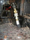 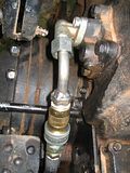  |
|
|
|
Post by bradblazer on Oct 9, 2008 22:27:12 GMT -5
Finally I added a 10um return filter and a quick connect branch for the backhoe return line. I'm thinking to run a bracket off the fender for support. While the tank was drained I also replaced that short 1" rubber section in the return line to the pump with hose actually rated for hydraulic oil. The old hose was cracked on the outside and blistered on the inside. I'll have go get pics of that next time. 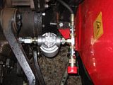 I did that in the rain last night. After parking outside in a spot that put the return inlet low to drain the tank I figured out I lacked a JIS adapter for the return hose. With the fluid drained I didn't want to move it so that pushed me into last night. I think the rain quit about 1/2 hour after I finished working under an old umbrella.  |
|
3RRL
Administrator  Huge Kama
Posts: 2,027 
|
Post by 3RRL on Oct 9, 2008 23:06:42 GMT -5
Wow, nice post Brad.
That's a lot of work you got done. This turned into a nice hydraulic system upgrade for you as well. I like the new location of the fel valve. I never liked where mine is located either.
That subframe looks very heavy duty. I'll be interested on your up front connections and connection to the backhoe itself. I see the lift arms will be used for your rear connection, right? If that's what you mean by it's going to be like a quick hitch.
One thing I can recommend, make sure wherever you plan to remove pins or bolts for subframe removal or connection to the tractor, give yourself plenty of room to get in and out of there. Not only that, but enough room to throw a wrench and maybe having to use a prybar and maybe a hammer. That hoe is giant and I know even with my smaller hoe, I wish I would've given myself a little more clearance for mounting and taking off. I had no idea I'd be using some of the tools (which I do) to get the thing on and off.
Rob-
|
|
|
|
Post by bradblazer on Feb 12, 2009 0:22:56 GMT -5
I've handled the Fein multimaster at the local WW show and it does make incredible plunge cuts plus it will not cut your skin (skin wiggles w/ blade) I have not seen the infomercial. The Winston HF store did not have any when I was there before Christmas. It didn't sound like they had seen them yet. I love my HF weedburner. I light it with an old fashioned torch sparker and it works good. I can have charcoal ready to cook in 5 minutes. I sinned at the Overstock store last week. They had an HF curb machine 94634 missing the rear guide wheel assembly and forms that had been sitting there for a while. I picked it up for $20. I'll have to price the missing parts or i can make them (someday). If nothing else it has a nice 3/4hp motor and worm gear box. Never been used and runs fine. Brad 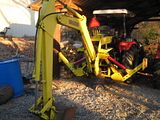 Hi Brad, Hope it's warmed up a bit for you. Great buy on the curb maker, hard to pass up a deal like that eventhough you have no use for it. I went into town to get Ed's magnets and to check out the HF clone MM, None in stock, I asked why? the response was - "we sold them all" I have to hand it to the clerk for being honest and a smart ass at the same time, I respect that. She also added, they sell like hot cakes and it's hard for them to keep in stock. Hey I see some progress on your monster BH. I could not help but notice the "Hydraulisized" out riggers. I think you invented that word right?  They do stick out a "little bit" though. I cant help ask why you didn't mount the cylinders such that the out riggers would fold straight up in the transport mode? Must be some sort of interference or lack of a good anchor point that prevented that? Larry Hey Larry, I'm replying here so I don't mess up the vital HF Multimaster thread. Thanks for the comments. You know curbing might be just the thing to keep the coyotes from digging under the fence. The word I made up is hydraulified. I would have said hydraulisized but I didn't know how to spell it.  Anyhow, I think it's a useful and needed word. I made some brackets and welded them to the stabilizers so they are straight at full extension of the cylinders. That part works fine but you are right - they stick out when retracted. I should have used shorter cylinders. On the bright side they should be plenty powerful and they have plenty of downward travel. Here is a pic I found of the OEM setup and I pretty much just tried to copy the geometry. farm1.static.flickr.com/70/160019516_f0f5b08012.jpg?v=0I think it would have stuck out some too. What do you think of the non-pivoting feet? I think I try them out before I decide whether to make swivel brackets. The stabilizers are really heavy. The feet are 1/2" thick plate with 2x2x1/2 angle iron cleats. 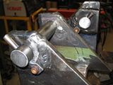  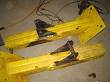 All of the hydraulics work fine now. Running the stabilizers off the remotes makes for a bunch of hoses. Still need to fab up the subframe. Brad |
|
GuglioLS
Administrator  Jinma354 LE
Posts: 1,276
|
Post by GuglioLS on Feb 13, 2009 0:47:27 GMT -5
"Hey Larry, I'm replying here so I don't mess up the vital HF Multimaster thread. "
I think you might have meant "virtual" HF Multimaster thread? with all the talk, I still don't have one.
"The word I made up is hydraulified. I would have said hydraulisized but I didn't know how to spell it."
hydraulified / hydraulisized - Tomato / Toe Ma-do same difference.
Nice build on the brackets Brad, I like the anti rotate keeper pins, did you maker those by smashing the ends using your press? And are those your CO2 MIG welds? They look great.
"What do you think of the non-pivoting feet?" Well I suppose it really doesn't matter all that much unless you encounter uneven ground or work on a slope. How often would you really be using a BH on a severe slope? I don't know. Perhaps add some sort of pivoting spikes to dig in a little? Pivoting feet may be over rated? I can see them coming in handy for when the outriggers were vertical in transport mode so they would not stick out as much. Small stuff compared to the challenge you have ahead making a sub frame or other form of "quick" and rigid mounting system to your liking. Got any digging projects lined up for it for when your done?
Larry
|
|
3RRL
Administrator  Huge Kama
Posts: 2,027 
|
Post by 3RRL on Feb 13, 2009 12:07:10 GMT -5
Hey guys,
I can tell you for sure that I work the backhoe on slopes and uneven spots. Sometimes when repositioning, one stabilizer hits on top of where I pile some dirt. Having said that, pivoting stabilizer feet ARE overated. I've had them fold backwards because they hit one stupid pebble so now the edge of the foot goes in. This happened even before I made the feet taller. I would think a fixed foot with a cross hatched bottom that sticks out past the bottom of the foot would work best. It would dig in when flat or on a slight angle. For sure it wouldn't flop over.
BTW Brad,
At the Tulare AG show, I saw how Kubota makes their frame mount backhoe. Especially with the size and weight of your giant hoe. It's a very rugged mounting system. You should search for photos on the net. I may even change mine out to what they have. It's an excellent yet simple system.
Rob-
|
|
GuglioLS
Administrator  Jinma354 LE
Posts: 1,276
|
Post by GuglioLS on Feb 13, 2009 19:39:19 GMT -5
Hey Brad, Here's a relatively effortless and inexpensive option to "stake" the outrigger pads 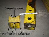 Larry |
|