3RRL
Administrator  Huge Kama
Posts: 2,027 
|
Post by 3RRL on Jan 28, 2008 3:21:59 GMT -5
I added two Andy Tatro Bucket Grapples to my Koyker 195 FEL bucket a while ago. Before I go into the details for those interested in making and adding them to their tractor, I am posting a short video to show what they look like and how they work. I used a "true third function" electric over hydraulic solenoid valve. It allows the use of curl/dump, lift/lower and open/shut the grapples simultaneously (if you have enough hydraulic flow or feather the valves). This is in place of using a solenoid "diverter" valve which causes loss of one of the other functions (usually the curl/dump) to use the grapples. The grapple cylinders are plumbed in "parallel" so when one hits an object, it stops but the other keeps going until it hits and object. It's designed to take into consideration clamping on irregular shaped objects. Anyway, here is a sneak preview of the completed project before I go into details.  |
|
3RRL
Administrator
Huge Kama
Posts: 2,027
|
Post by 3RRL on Jan 28, 2008 18:33:35 GMT -5
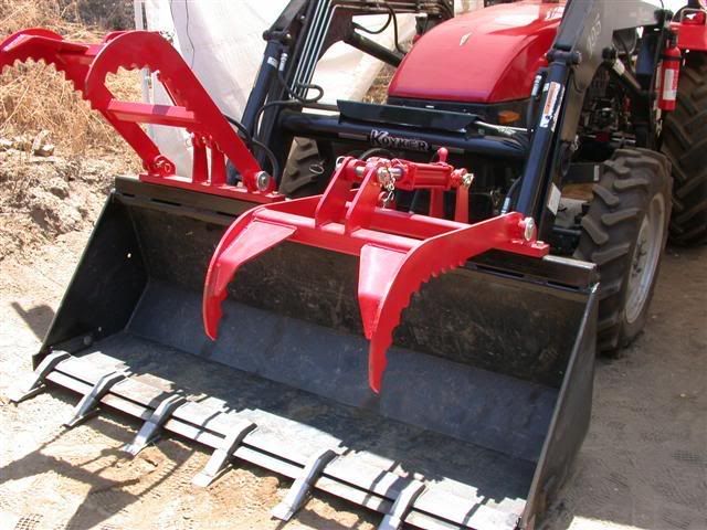
After getting all that good advice on how to hook up the hydraulic valve, I'm ready to start with my "Add-a-Grapple" project. I have done several modifications to my tractor and implements, but this was the first time messing with adding a hydraulic valve. I started out by asking questions about grapples to add to the bucket. I didn't want to buy a complete rock bucket grapple because it was pretty expensive especially shipping on top of that. I also didn't want to change the bucket because I'd have to make a "quick attach" system for it. I have not had to take the regular bucket off so far and really don't intend to. After much investigation and advice, I decided on the Andy Tatro bucket grapple. He makes a very nice one and it suited my "eye" more than the others. I especially liked the shape of his curved arms and teeth. He made the arms custom so they would meet the cutting lip of the bucket. His fee for the grapple and hydraulic cylinder and shipping was $450 to my house and shipped promptly within a couple of days. Here's the first couple of photos for now. My bucket is huge (½ yard) and the loader has a 2500lb+ lifting capacity, probably more because I have flattened out both front tires (loaded) with enormous loads in it.  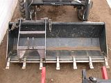 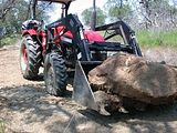 At this point, if you look closely, the grapple is just clamped on for now. Andy Tatro drew up the movement of the arm clamps and suggested to get a 3" x 3" square tube ¼" wall to raise it off the top of the bucket. He said most buckets that are as deep from front lip to back are taller than mine. So I have to get the square tubing first to raise it up. I positioned this one in the center at first but realized it seemed rather small. So I moved it to one side to see what it would look like. Since my bucket is so huge, I was considering getting 2 of them. They would fit nicely with a 12" gap between them. I contacted him (Andy) about it and he said it would work. You may have seen some grapples that sport 2 sets of clamps? This set-up would be like those. I would plumb the hydraulic cylinders in parallel so that when they start to clamp down, they can clamp on odd shapes simultaneously. For example like a tree trunk or boulder that was shaped like a bowling pin sitting lengthways in the bucket. As the clamps started downward, the one around the bigger diameter would stop while the one on the smaller diameter would keep going until it hit, then both would get tight as they meet resistance. The one with the less resistance would keep going until it gets as tight as the other one. When opening up, the one that reaches the maximum opening would stop and the other would continue until it reaches it's maximum. |
|
3RRL
Administrator
Huge Kama
Posts: 2,027
|
Post by 3RRL on Jan 28, 2008 18:34:46 GMT -5
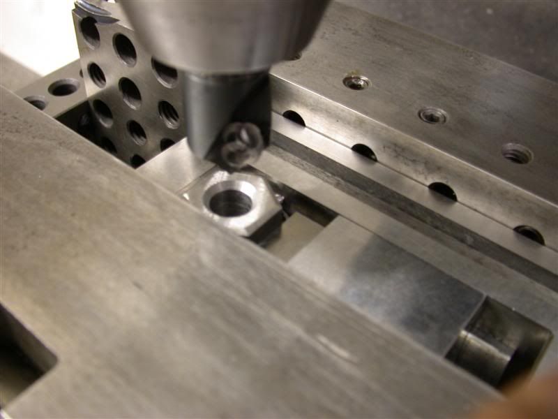
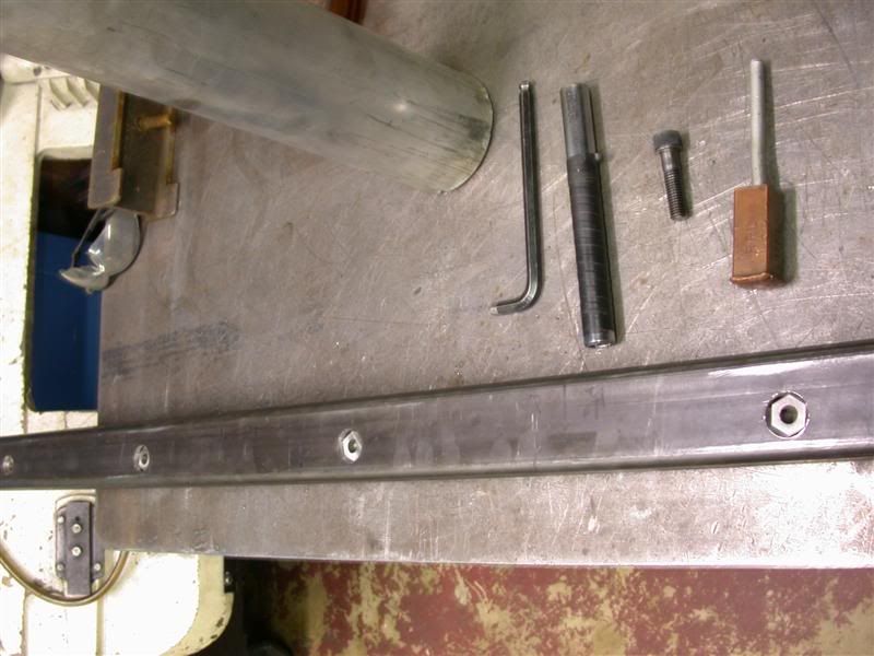
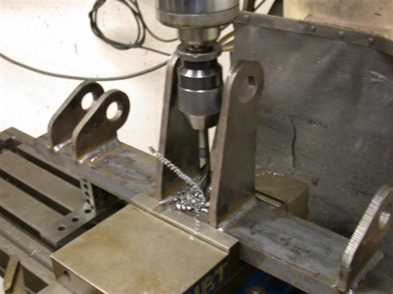
I started piddling on the 72" long 2-½" square tubing that will suspend the grapple base from top of the bucket so the curved arms will have more capacity. I decided to install home made threaded nuts inside the bar to bolt the grapple base to it. Here's a picture of the bar being drilled in one of my mills. 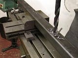 My plan is to make the nuts so they will fit snugly against the inside of the upper tube wall and I'll weld them on the bottom to the tube. That way when I close the grapple on something, both walls of the tubing are retaining the nut instead of just one wall. It will be much stronger that way. |
|
3RRL
Administrator
Huge Kama
Posts: 2,027
|
Post by 3RRL on Jan 28, 2008 18:42:39 GMT -5
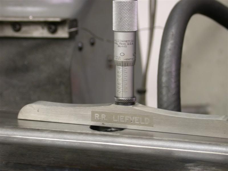
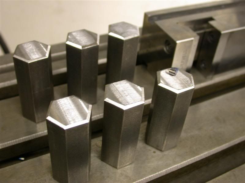
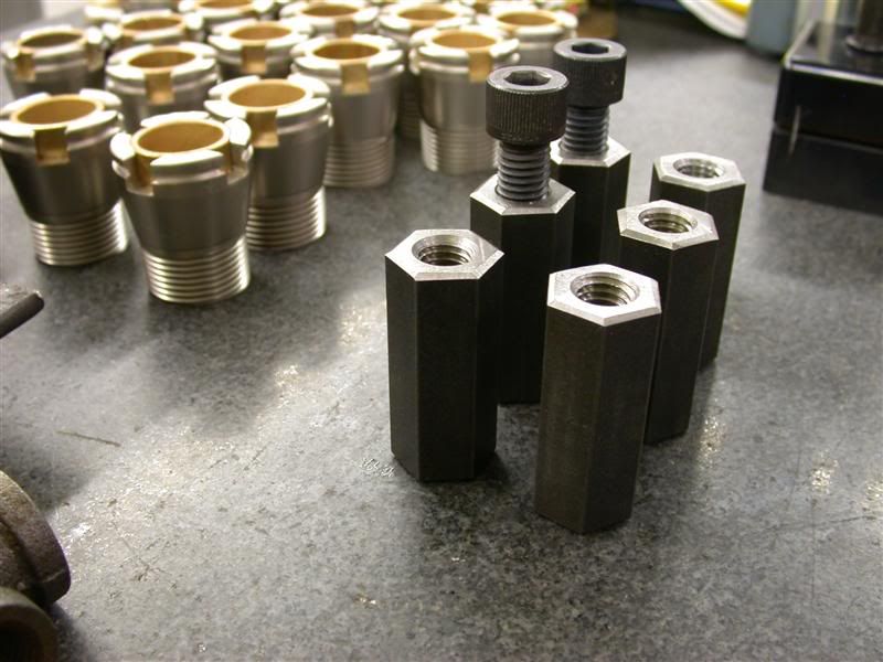
It's easy to take for granted the nuts and bolts we buy. They are made with high production techniques and are pretty cheap to buy. But try making them yourself from scratch...especially ½"-13 ones that are 2-¼" long. These are more like coupler nuts for clamp-down kits. I made 6 of them. First, I had to depth mic the pocket in the bar to determine the length needed. They will be sub-flush so I can weld over them. Probably not critical at all, but I like to make sure anyway.  Then I had to saw off 6 pieces about 2-3/8" long from a bar of 1" hex stock. Then mill one end on each, chamfer, flip over, mill other side to length. 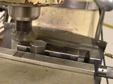 Here they are to size, all deburred and chamfered...ready to drill and tap. Notice the chip on the last one. 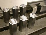 |
|
3RRL
Administrator
Huge Kama
Posts: 2,027
|
Post by 3RRL on Jan 28, 2008 18:46:54 GMT -5
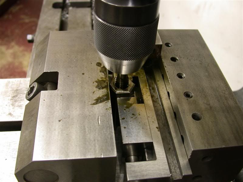
Then I moved to the other mill where I had my giant precision milling and grinding vise set up. Then I countersunk the hole. Here is one being countersunk. 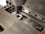 Then I set up to tap them all....same vise set-up. Power Tapping them. 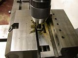 I first thought of using coupler nuts from one of my clamp kits but then I would have to make spacers to have the fit the way I wanted. Here they are all finished and ready to weld into the riser bar. A lot of work for some stupid nuts. But, they are perfect for what I wanted. 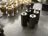 |
|
3RRL
Administrator
Huge Kama
Posts: 2,027
|
Post by 3RRL on Jan 28, 2008 18:48:57 GMT -5
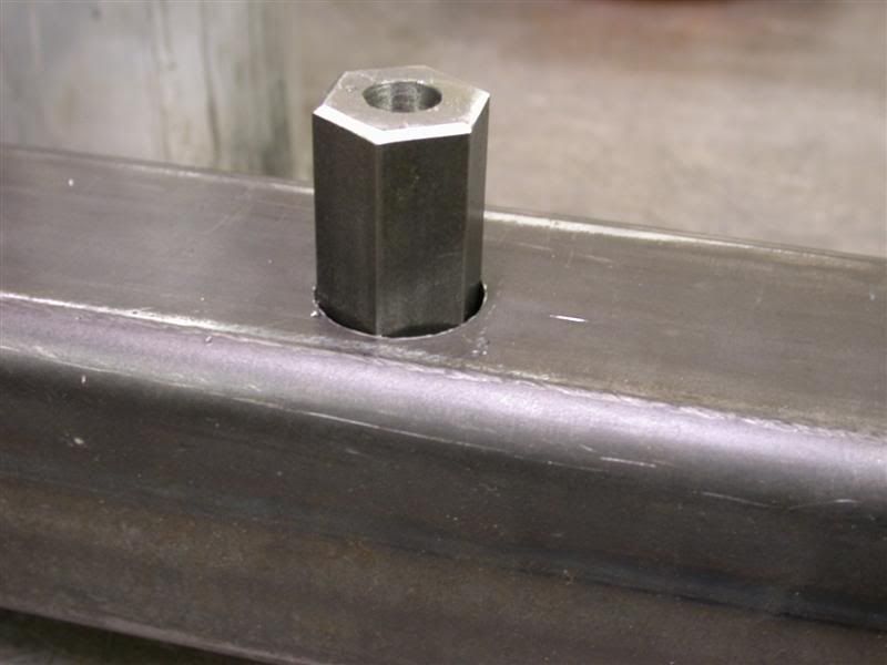
The nut will not go all the way through. The top of the tubing has a clearance hole (Ø9/16") and the bottom has a Ø1" hole. The nut will be pushed through the big bottom hole until it butts up against the inside of the top wall. Here it is going into the big bottom hole. 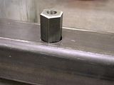 Then I use a bolt to suck it up super tight against the top wall like this. 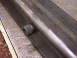 That will keep the nuts in place so I can weld the bottom wall of the tube and the nut together. In this picture you can see the bottom of the nuts and the big bottom hole. Notice how there is a recess that I can fill up with weld. 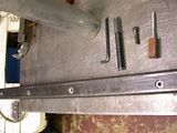 What does this do for me? Well, in this manner the nut is "fastened" to both walls (top and bottom) making the connection of nut to tube double strong. Theorhetically, if I used only one wall, that tube wall may "flex" when I tighten the grapple base to it. In the real world it may not make much difference but in my mind this is a stronger connection. In other words, to break loose the nut, I would literally have to "suck" the 1" hex nut through the Ø9/16" top hole...that will never happen! |
|
3RRL
Administrator
Huge Kama
Posts: 2,027
|
Post by 3RRL on Jan 28, 2008 18:54:07 GMT -5
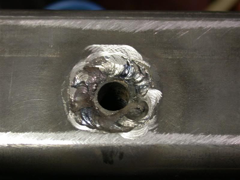
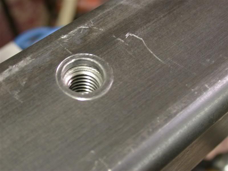
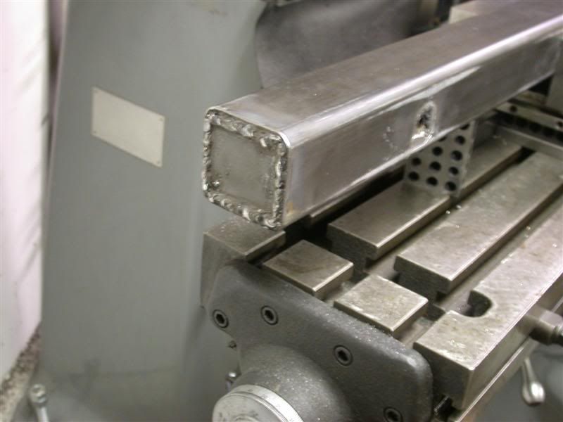
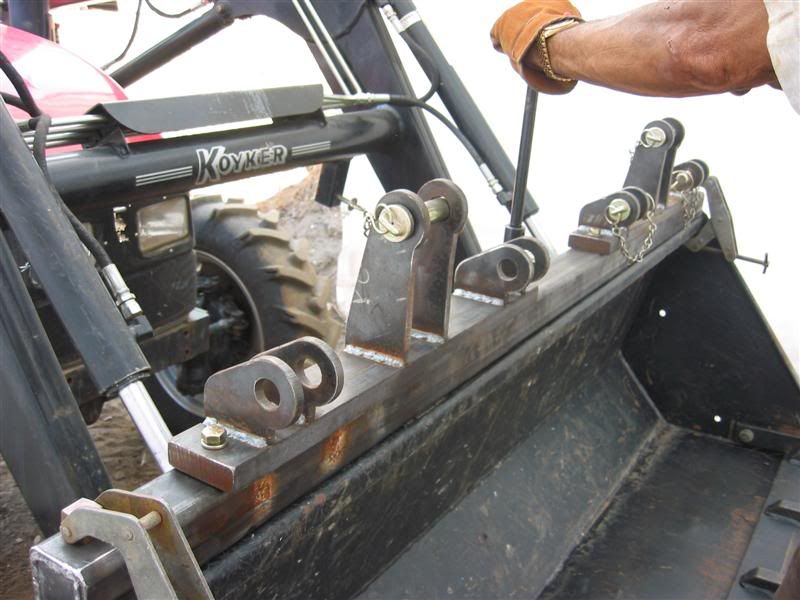
I made some progress and finished the support bar (square tube) that the grapple base will sit on. I'll weld this bar onto the bucket and then bolt the grapple and base to it using the nuts I made. This will allow me to remove the grapple(s) when I don't need them, leaving only the bar on the bucket. This pictures shows the nuts now welded into the bar tube. This is the bottom that will sit on top of the bucket. All welds are with my old Forney arc welder using 6011 stick so they are not the prettiest. (Too lazy to hook up my Miller 330 A/BP Tig welder) 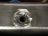 Here is what the top will look like. If you look closely, you can see the threads in the nut under the tube wall. The holes are offset from centerline of the tube to allow the grapple base to sit forward a bit. 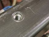 I also decided to cap the ends so no dirt gets in there. When painted, this will look pretty good. It will also keep the ends of the tube from getting crushed and flattening out by accident. Next step is degrease the tube and primer it. I'm also going to make some brackets that will hold the quick disconnects. 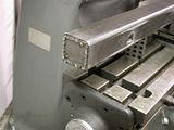 |
|
3RRL
Administrator
Huge Kama
Posts: 2,027
|
Post by 3RRL on Jan 28, 2008 18:56:38 GMT -5
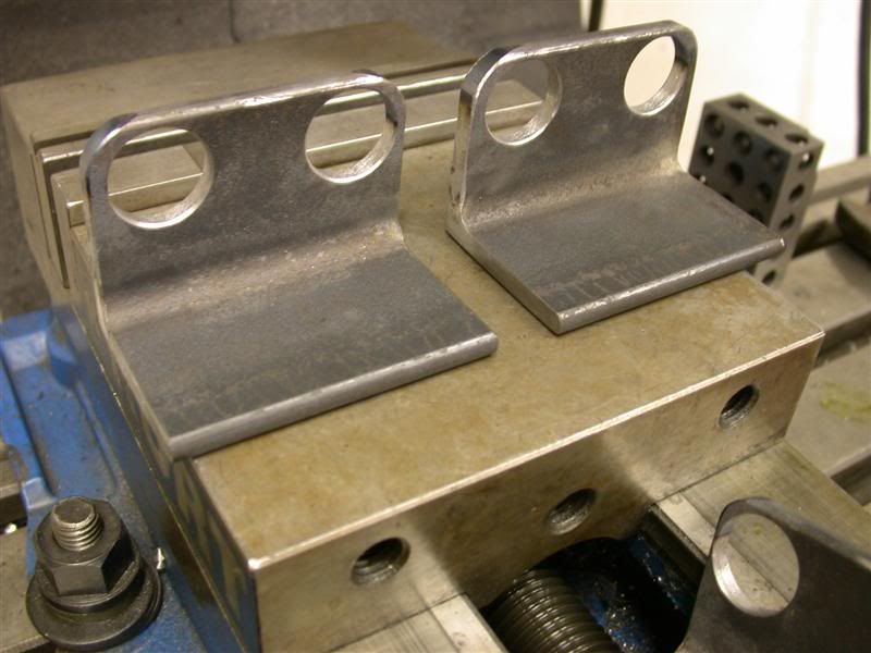
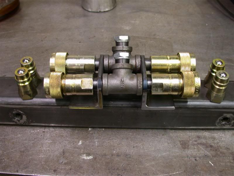
I got the grapple base drilled with clearance holes. There will be (3) ½"-13 grade 8 bolts holding each base to the spacer tube. This picture didn't come out very good. 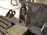 I also made the brackets that will hold the quick disconnects and maybe some 90° elbows... so I ended up making 4 of them total. The holes are just large enough for a ½" pipe to swivel in them. This will help when the hoses flex around.  This last picture shows the "T"s between the brackets. The "T"s are to split the flow between the two cylinders hooking them up in parallel and allowing them independent travel (bottom out point). I will probably bolt or weld the brackets to the spacer bar. I have to look at a bunch of bucket/loader pictures to make sure they will be mounted in the best spot. 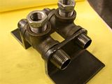 |
|
3RRL
Administrator
Huge Kama
Posts: 2,027
|
Post by 3RRL on Jan 28, 2008 19:03:12 GMT -5
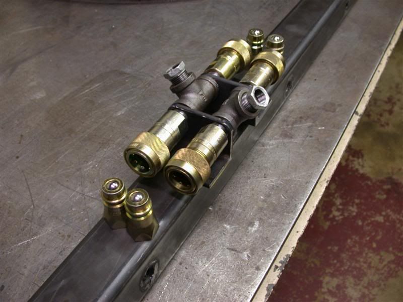
I might as well tell you that I used black pipe for some of my fittings and elbows. At the time, I didn't know where to real hydraulic elbows but I do now. I don't recommend using black pipe since the psi rating is not up to hydraulic pressures, however I have used them in the past with no failures. OK, I got my brackets done and then drilled bolt holes in them and the spacer bar. I thought it best to bolt them on instead of welding because I may want to extend the quick disconnects from center using longer pipe nipples. This would put each set a little closer to each grapple cylinder allowing shorter hoses. 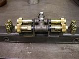 Here they are mounted to the spacer tube. Notice how they can swivel (rotate) if need be to self align with the hoses from the grapple as the bucket and jaws move. I thought this might be a pretty good idea. Now I realize I could have bought swiveling elbows to do this. 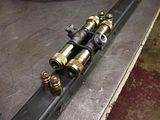 This picture shows the grapple base bolted down to the spacer bar. The quick disconnects are in the center and behind the spacer tube. The other grapple has not arrived yet. 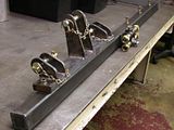 When it and the hydraulic cylinders arrive, I can drill that mount too and then measure for hose length needed. I buy my hydraulic hoses at Agri-Supply. They are by far the most reasonable price and if you design around them, they will work in most any case. You can get the stock ones in 3/8 or 1/2"NPT ends (one swivels). The hoses that connect to the valves may need different fittings and I plan on getting those once the up front stuff is done and mounted on the tractor. |
|
3RRL
Administrator
Huge Kama
Posts: 2,027
|
Post by 3RRL on Jan 28, 2008 19:05:00 GMT -5
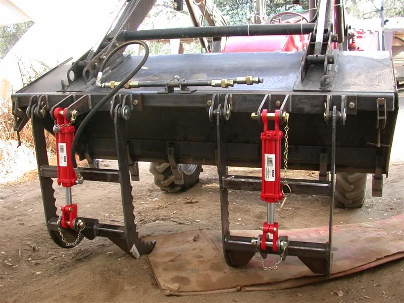
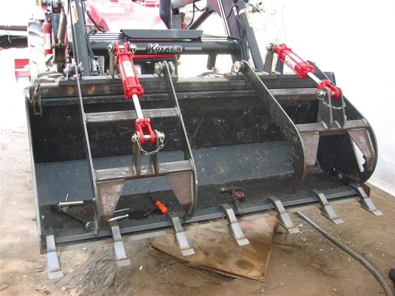
I went up to the property with Loretta (Mrs 3RRL) and she helped me start the 2nd fitting and measuring process on the grapple project. The temperatures were 112° on Saturday and cooled down to 110° on Sunday. As usual, we only have 1-½ days to do any work. In between, I also cleaned/graded the homesite pad and solar shed area. So I did get some seat time too. After hauling all that steel from the garage up, I was able to clamp the spacer bar to the top of the bucket and start some assembly to see how everything would fit. This was a redundant but important step because it will tell me what the correct and best position the grapples will sit. It also will tell me the correct length of the hydraulic hoses. All bucket and loader arm movements must be taken into consideration to allow enough hose for travel, yet not too much so it doesn't "bunch up" or kink. To start, here is a picture of the grapples kind of what they will look like mocked up on the bucket. This gives you an idea of what it will eventually look like. 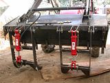 I started by clamping the spacer bar on the top of the bucket and then bolted the grapple bases to the spacer bar. I had predetermined there location so as to avoid hitting the tooth bar teeth. I wanted about a 14" to 16" gap between the two jaws. 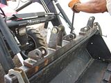 |
|
3RRL
Administrator
Huge Kama
Posts: 2,027
|
Post by 3RRL on Jan 28, 2008 19:07:00 GMT -5
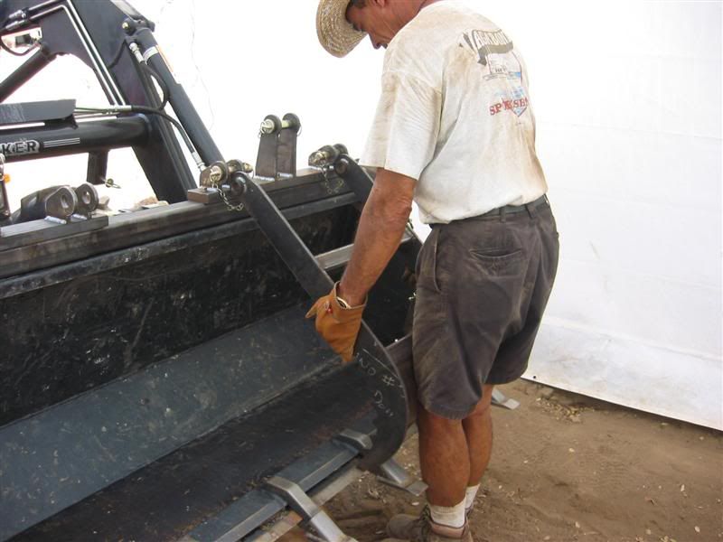
Then I tried to fit the jaws onto the base. 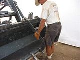 This will tell me how the jaw relates to the bucket and whether it interferes or not. If I don't like the position, I can alter the location slightly at this point. 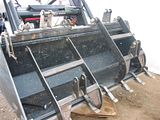 You can see that one grapple is pinned and the left one is not. I had read that the grapple jaws should come out to the end of the teeth. But after thinking about it, I thought it would be better to have the jaws be able to close "inside" the bucket. This would allow the jaws to grab or crush any brush or debris into (inside) the bucket. The travel of the jaws (range of motion) will also be dictated by cylinder stroke. Otherwise, if the jaws stopped or hit the front teeth, some brush and stuff might fall out of the bucket...not clamping it. Gee, I really thought I came up with something important. I thought about it and realized the "reach" of the jaws would be a little less, but I guess being able to "clamp down" on stuff inside the bucket might be more important to me? I accepted the fact that the jaws opened up big enough to grab an object that I could probably not pick up anyway!!! Then I noticed that the pinned and mounted jaw on the right did that....exactly....hahaha....so Andy Tatro did his homework correctly and the jaws fit nicely inside my bucket. That is why he told me to make that spacer bar. Otherwise, if the tip of the jaws hit the bottom of the bucket, they would tear a hole in the bucket....duh.... |
|
3RRL
Administrator
Huge Kama
Posts: 2,027
|
Post by 3RRL on Jan 28, 2008 19:08:57 GMT -5
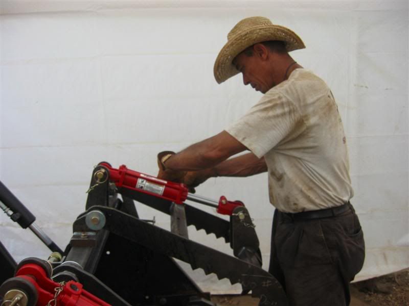
The next thing to do was to install the hydraulic cylinders. They were supplied by Andy Tatro. They are Ø2" x 6" stroke with Ø1-1/8" rods. Their brand name is Chief (made in India) and they were drop shipped to me from Surplus Center. They look like pretty good cylinders and best of all, I like the color.  One thing, the cylinders are identical so when I put them on with the rear ports (clevis end) pointing upwards, the rod end port on one pointed to the inside of the bucket and the other one pointed to the outside of the bucket. So I'll have to do is dis-assemble one of the cylinders and rotate the rod end 180° so that the ports on each cylinder point to the inside of the bucket. This way my hoses will be equal length on both sides. Most important, they will look neat and symmetrical....having a balanced appearance to the eye. |
|
3RRL
Administrator
Huge Kama
Posts: 2,027
|
Post by 3RRL on Jan 28, 2008 19:10:41 GMT -5
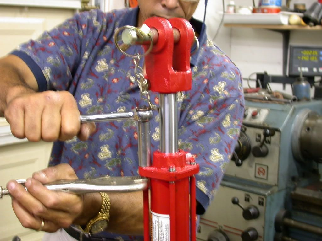
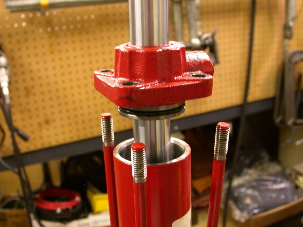
These pictures show the process of rotating the ports to your liking. It is relatively easy to do with cylinders that are bolted together like these are. This shows the original cylinder. Note the upper and lower port locations....both are pointing to the left. BTW, the clevis end has 2 port locations on it, 90° apart. 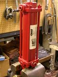 This picture shows me disassembling the cylinder. Remove the nuts and pop off the rod end cap. 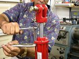 Then separate the rod end cap from the cylinder body. It is "O" ringed for a leak proof seal. This has now been rotated 180°. Note the orientation of the top port to the bottom port now. 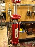 This is a close up of the rod end cap. When done, line up the bolts and ports and bolt everything back together. Now the ports will face in the direction I want. Oh, I forgot to add to remove the port plugs to relieve any vacuum or pressure build up. That allows you to pull the rod out etc.  |
|
3RRL
Administrator
Huge Kama
Posts: 2,027
|
Post by 3RRL on Jan 28, 2008 19:15:15 GMT -5
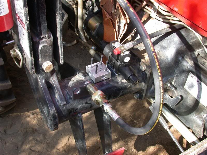
Meanwhile back at camp, I had to measure for hose length. I wanted to use the minimum length to meet the maximum travel (movement) of the jaws, the bucket and loader arms. I had done this before so I could order the hoses from Agri-supply, but my measurements were long on purpose. The picture below shows only one hose to each connection. The hose coming from the hydraulic cylinder to the Quick Disconnects is on the lower left hand corner and the hose from the parallel ports are to the loader. I chose this method so I could add 90° elbows or 45°'s if they made for better rotation and function during operation. My goal is to have the hose bend and buckle in a desired direction out of harms way. Notice also that I now extended the QD's to get closer to each cylinder. Also notice how one hose follows up the loader arm back to the quick disconnects where the loader can be taken off the tractor if need be. 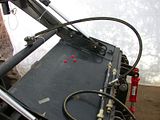 I tied off that long line (obviously there will be 2 of each when done) and found it to be pretty close as how I pictured it going to the loader frame and where the third function hydraulic solenoid valve will be mounted. There will be a whole bunch of hoses in this area. Here's a picture showing approximately how I'm planning to mount the new valve. 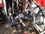 In that photo, the long lines coming from the bucket will have quick disconnects. They will attach via a bracket I have to mount on that loader frame. Then they will connect to the solenoid diverter valve (which I have to make a bracket for too). Notice the aluminum block (valve mounting base) that has holes on top and tapped holes on the sides. The valve sits (bolts on) this piece and the hydraulic hoses thread into all 4 sides of it. You must buy it along with the solenoid valve. Two holes will go to the hoses for the grapple cylinders and the other two are the "pressure in" coming from the power beyond on my loader valve and the other is "power out" continuing to the next valve in series. So you can see, I will need a couple of short lines to connect the QD bracket (the part that stays on the loader frame) to the aluminum block. This leaves the long hose to come off with the loader arms if I ever need to remove it (the FEL) from the tractor. |
|
3RRL
Administrator
Huge Kama
Posts: 2,027
|
Post by 3RRL on Jan 28, 2008 19:18:31 GMT -5
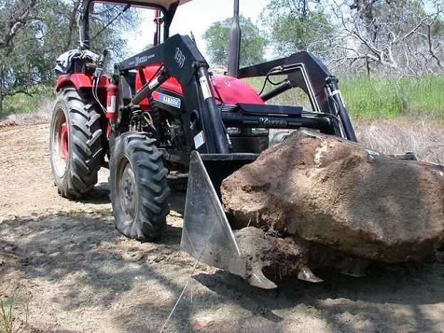
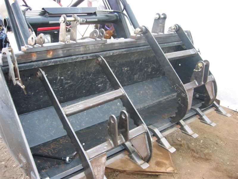
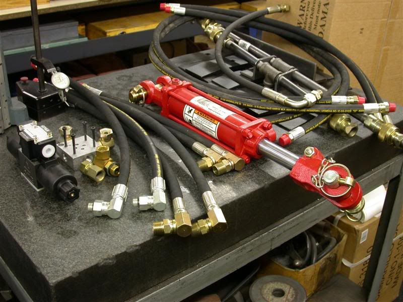
This is another photo of when I first put the grapples on. I tried to get the jaws to sit at different clamp height for the picture to show how...possibly...they might act when I pick up a rock or log with a weird shape on it. 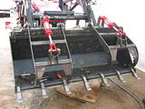 I had told you I bought the hoses from Agri-Supply and that I got them extra long on purpose. I figured on cutting them to length and installing new correct fittings instead of the 3/8" NPT that came on them. I bought 2 twelve footers that run along the loader arms and they will stay that way. Then I bought 2 six footers that go from the power beyond to the new valve and back again to the next valve in in series. These two needed different fittings to connect to the new and old valves. They needed 1/2" JIC fitting, and 3/8" JIC to work, male and female and an elbow on one. The hydraulic company I go to had all those adapters that fit the 3/8" NPT ends so I didn't have to cut those hoses. 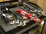 All the other hoses were made from 4 four footers. I cut them to length in the garage today and had them put on the new ends for me. Now there are 12 new hoses altogether. The Agri-Supply hoses were from their stock 4500psi Hydra-Light 3/8" two wire hose (made in USA) which cost me $127. The hydraulic guy (U.S. Hose, Inc.) charged me $182 for ALL fittings, installed. So for $309 I got 12 hoses with swivel connections and elbows etc., most were custom length for this project. that's quite a savings if you consider a short made up hose with swivel ends might cost $40 or more each! |
|