PJ
CTW Expert

Posts: 176
|
Post by PJ on Nov 27, 2009 6:55:53 GMT -5
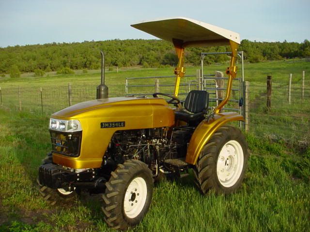
I remember reading about the Cray 1 in Popular Science. Now I have several of them on my desktop. I like the new avatar. Cool bubble canopy. You should start a thread about it. A Cray 1 on your desktop? You sure must have one BIG desktop! Only joking.  The guy was a genius, no doubt about it. The guy was a genius, no doubt about it. |
|
PJ
CTW Expert
Posts: 176
|
Post by PJ on Nov 29, 2009 9:19:51 GMT -5
Brad, how's the grapple coming along? Any more photos? PJ
|
|
|
|
Post by bradblazer on Nov 29, 2009 21:27:54 GMT -5
|
|
|
|
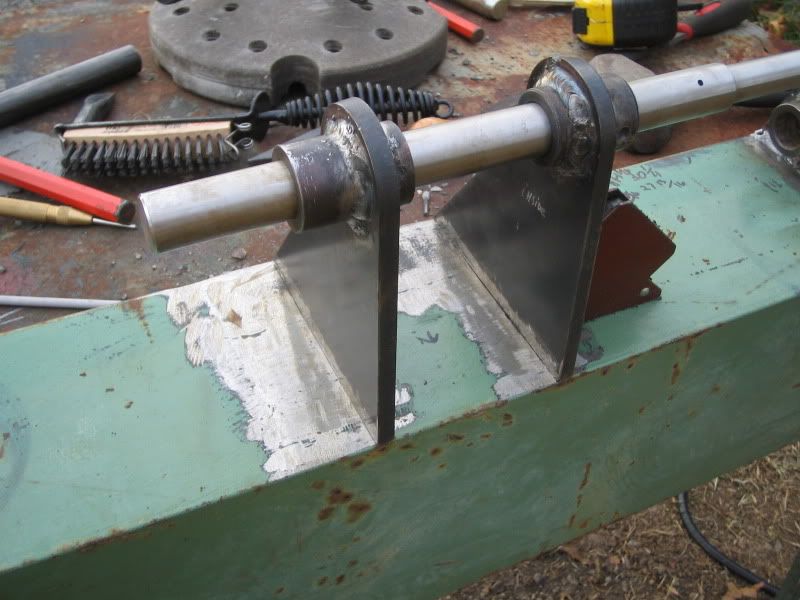
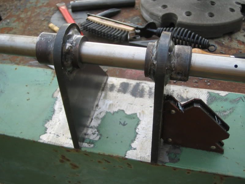
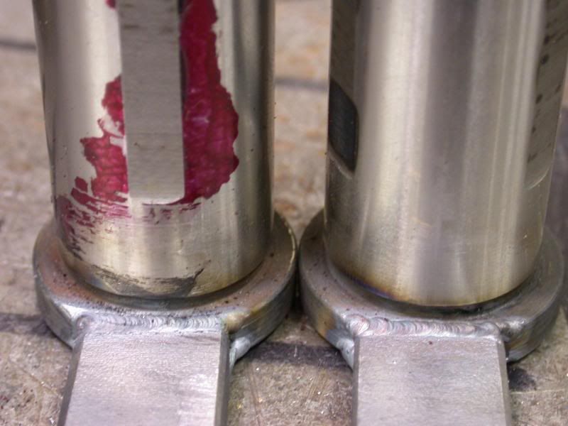
Post by bradblazer on Nov 29, 2009 21:37:59 GMT -5
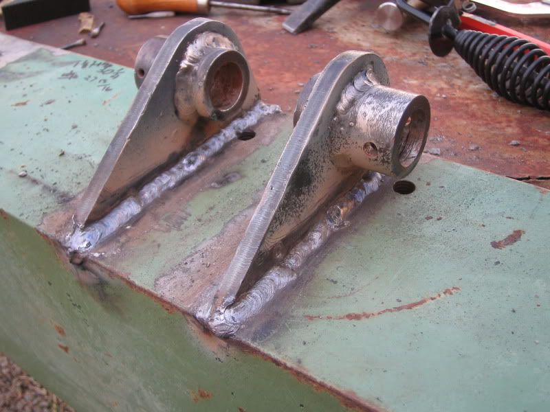
I had a back spasm as I was welding and had to take a break.  When I got back to it there wasn't much left. You can see the unwelded portion of the near bracket. That little nub on the left is where I stuck the rod when by back gave out. There's also a little inclusion on the left end of the second bracket that I will fill in. 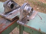 I decided to take some video. Sorry about the crappy videography of the second one where I am holding the camera in my left hand and chipping with my right.  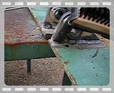 |
|
|
|
Post by bradblazer on Nov 29, 2009 21:50:23 GMT -5
|
|
GuglioLS
Administrator  Jinma354 LE
Posts: 1,276
|
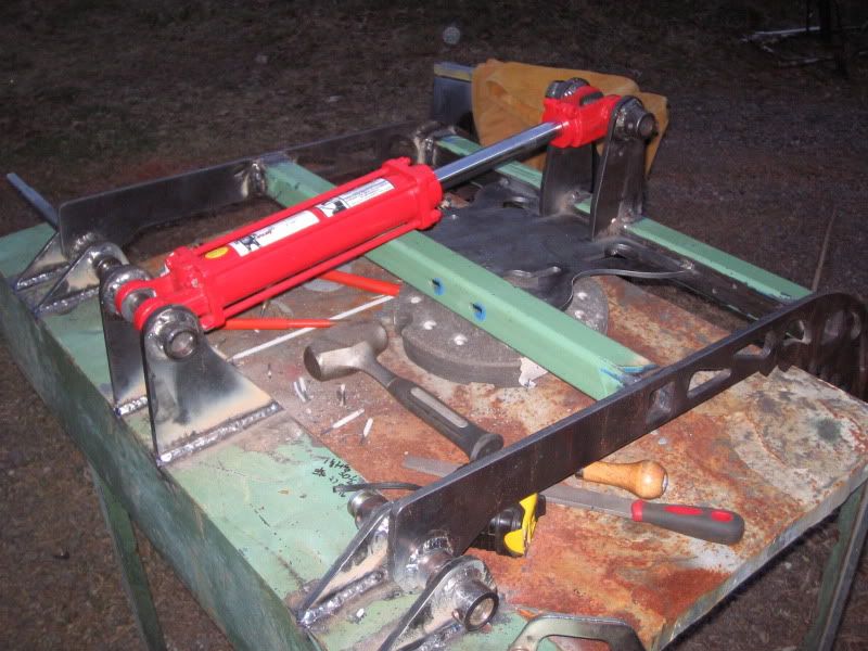
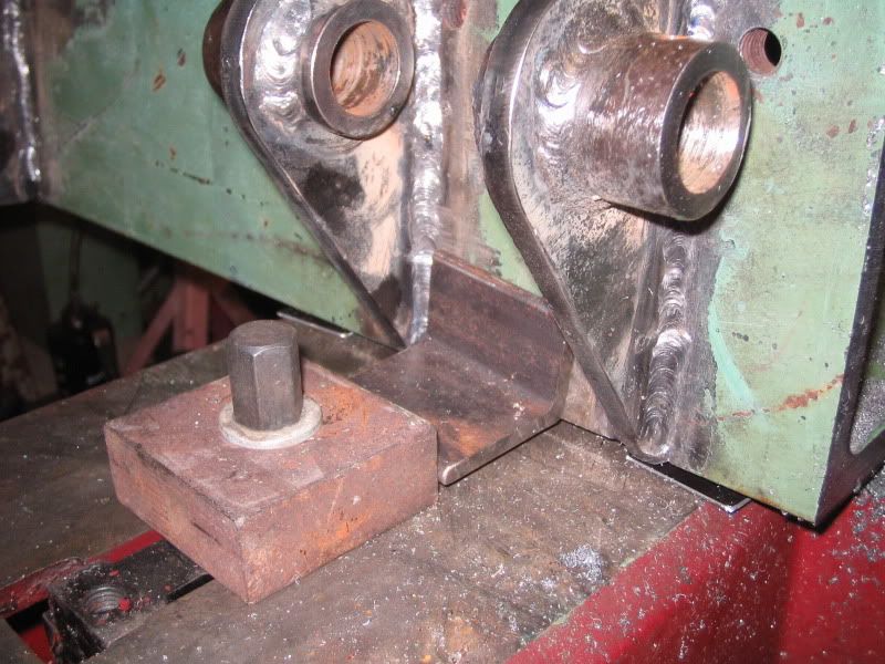
Post by GuglioLS on Nov 30, 2009 10:19:01 GMT -5
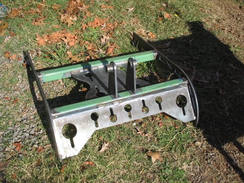
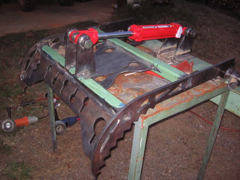
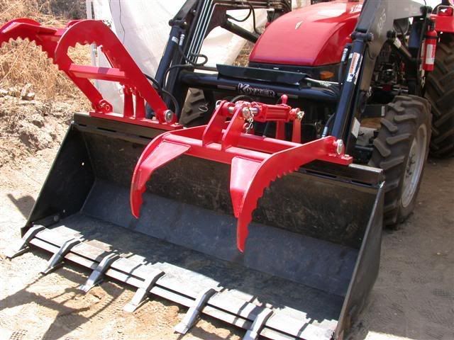
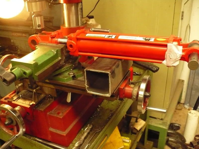
.........Snip........Snip.... Larry, remember that close tolerance you pointed out between the cylinder body and square tube? Check out the 6th pic.  Brad I remember that, looks close. Anything other than touching is considered clearance in my book. Obviously the result of great planning and execution. Looks fantastic (and really heavy duty too)! All the brackets and bushings came out nicely aligned. Good idea using 1" OD solid bar as an alignment jig. I suppose your going to make your own pins to replace those 1" bolts? I like the video chipping off slag. The angle iron has a nice deep ring tone, it sounds like a well tuned bell. I see the weather is cooperating so keep the progress reports coming. Larry |
|
|
|
Post by bradblazer on Dec 4, 2009 9:28:17 GMT -5
Thanks Larry - All of those beautiful plasma cut parts really helped it go together nicely.
I'll use some of that round stock to make the pins. Just cut them to length and drill a clearance hole for the 1/4" capture bolt.
I have plan for the grease zerks a little different from your thru-pin method. (I'll let it be secret for now.)
I made it to the shop last night but all I did was make 2 bandsaw cuts. (cut the ends off the big angle iron) It's interesting that to approach the advertised cut dimensions of my bandsaw I have to remove the vise.
|
|
GuglioLS
Administrator
Jinma354 LE
Posts: 1,276
|
Post by GuglioLS on Dec 5, 2009 0:41:49 GMT -5
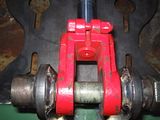
.....Snip.....Snip...... It's interesting that to approach the advertised cut dimensions of my bandsaw I have to remove the vise.  Same thing here Brad so I know the feeling. On mine the vice as two positions, 1. "normal" so that it can be angled up to 45* and get a full width cut. OR 2. Set back so as to get the full advertised 12" width cut at a 90* If at all possible, I leave it in "normal" and at a 90* angle because I dread having to re-align it to the blade. I'm sure like you, most of the time all we want are perfect 90* cuts. Because of that when cutting 45*'s most of the time I jury rig it with a V block or other means instead of changing the vice angle. Well I sure do look forward to seeing your secret grease-able pins. I spent allot of time farting around making mine for the grapple. The ones I made for the skid steer plate were allot easier and made more sense than what I did for the grapple. I thought this idea was kind-a cool, instead of grease-able pins put fittings right on the jaw pivot ends: 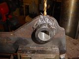  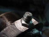 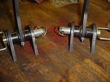 Larry |
|
3RRL
Administrator
Huge Kama
Posts: 2,027 
|
Post by 3RRL on Dec 5, 2009 9:56:23 GMT -5
Hi Brad, Great progress you are making on your "Star Wars" bucket grapple. Like Larry, I too am looking forward to your secret way of greasing those bushings. I'm sure you saw how I made Loretta's greasable pins and bushings. I recessed the Zerk fitting into the pin. I did the same for those QA Gauge Wheels and other projects. I put one hole in the center of the pin (not all the way through) and then counter bore and tap it so the Zerk sits completely in the counter bore. 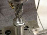 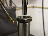  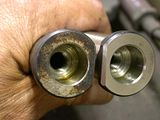 Then I put 2 or 3 flats on the pin for only the length of engagement. I stay a little shy of the ends so grease does not follow the flat out the end. Then I drill cross holes to intersect the main center grease line. I also made a counter bored hole for a low head socket screw to attach and retain the pin and keep it from spinning or falling out. The grease gun tip fits into the counter bore and over the hidden Zerk fitting. 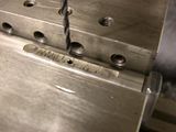 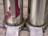  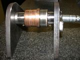 This method has worked for many applications keeping the Zerk safe yet accessible regardless of the position of the jaws. I'm keenly interested in your "secret" and hope to see it soon! Regards, Rob- |
|
|
|
Post by bradblazer on Dec 7, 2009 0:50:37 GMT -5
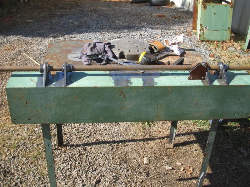
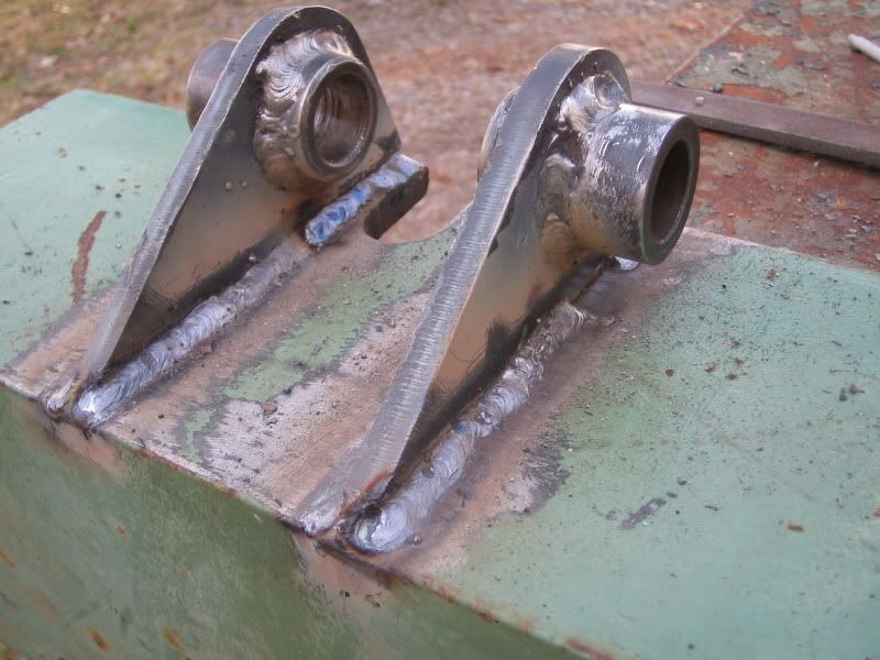
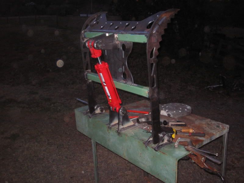
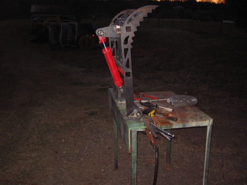
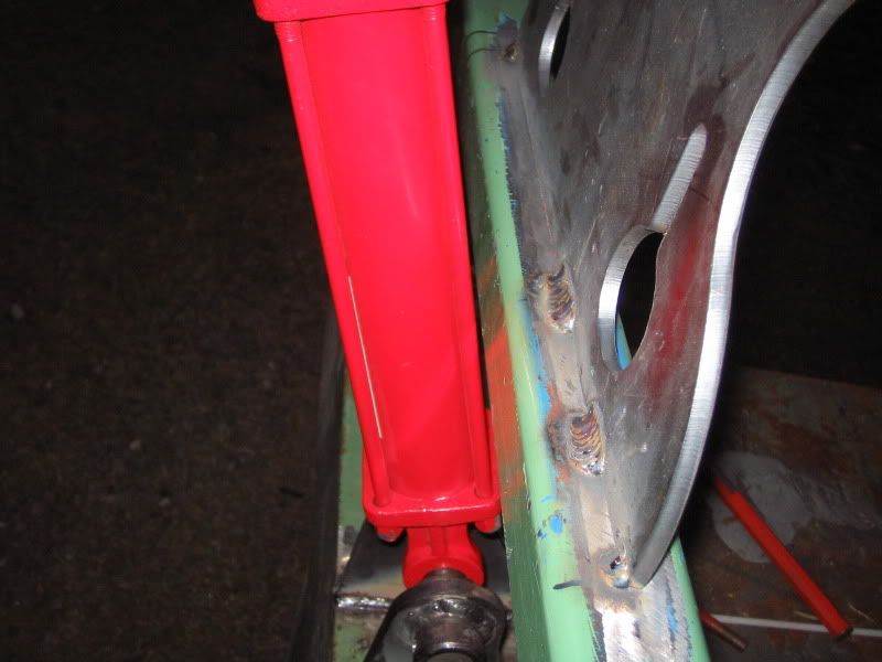
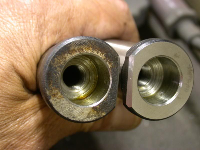
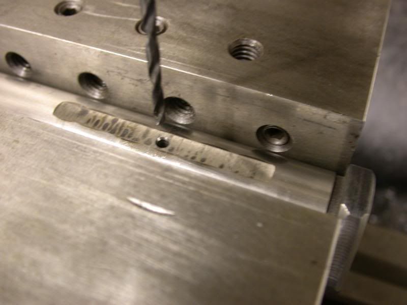
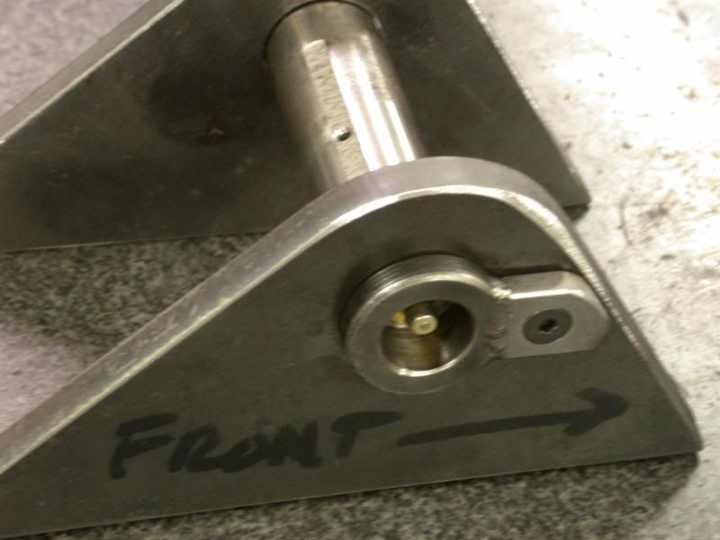
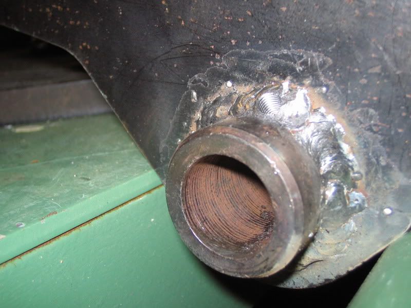
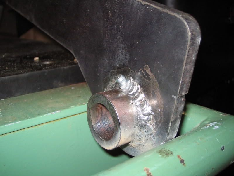
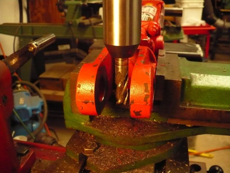
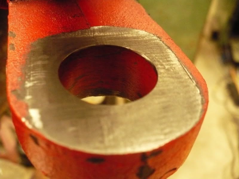
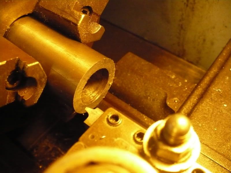
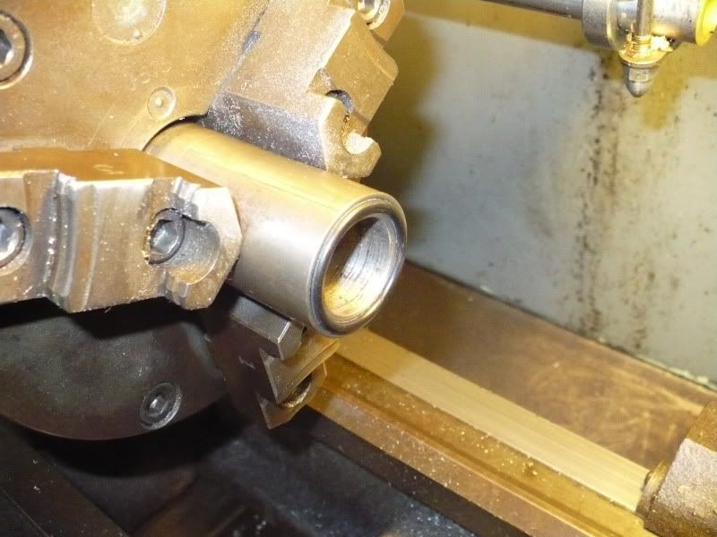
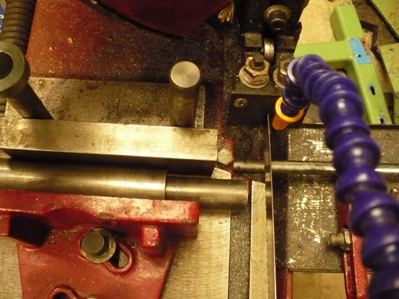
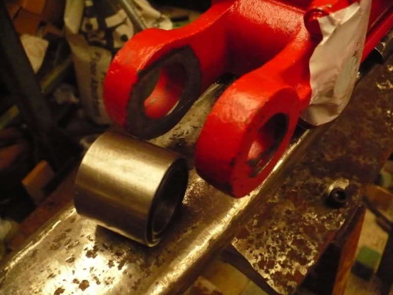
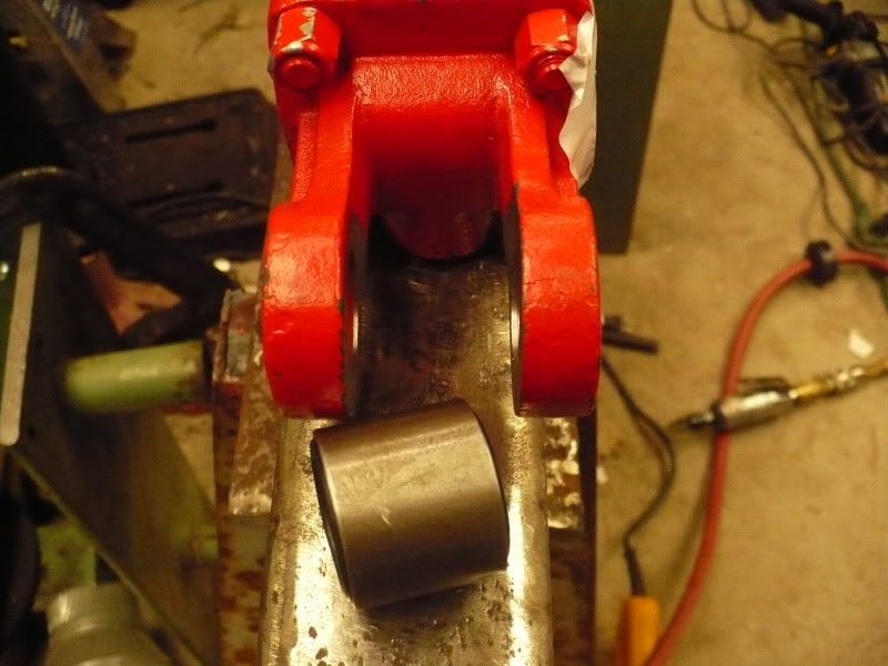
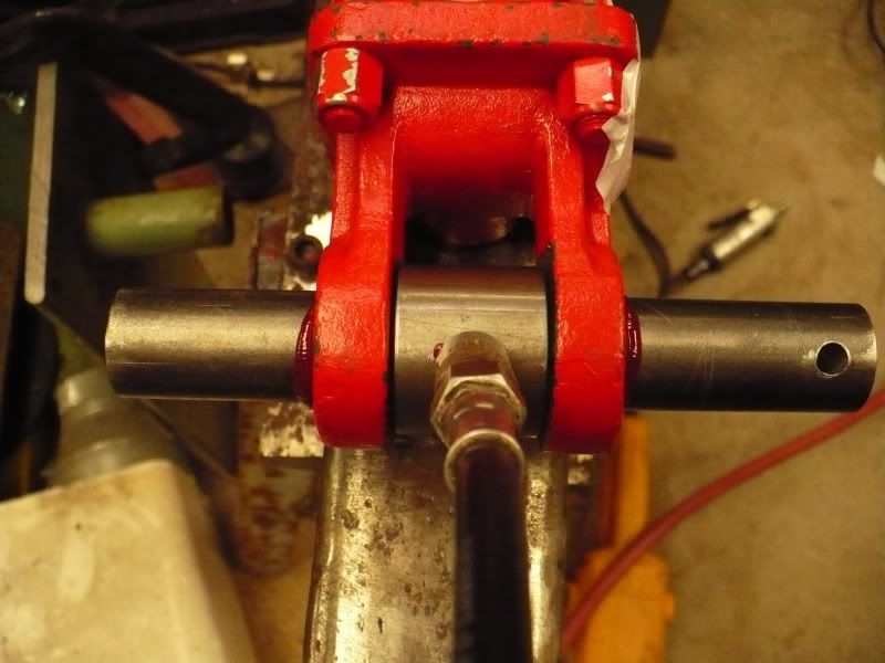
Thanks Larry and Rob for the nice pictorials. Here are some pics of my sawing setup. I have so much junk.. (How much junk is it?) I just happened to have a couple of Nextrom extruder clamp support rods with threaded ends that perfectly fit the vise jaw mount holes on my Chinese bandsaw WITHOUT MODIFICATION.  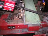 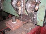 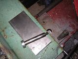 I mounted my zerks for the grapple pivots similar to Larry's except that I drilled right through the welds at about a 45 degree angle. I just filed a little flat spot, center punched them and drilled them with a hand-held drill. That makes the zerks fairly well protected and easy to access.    |
|
|
|
Post by bradblazer on Dec 7, 2009 1:22:52 GMT -5
|
|
|
|
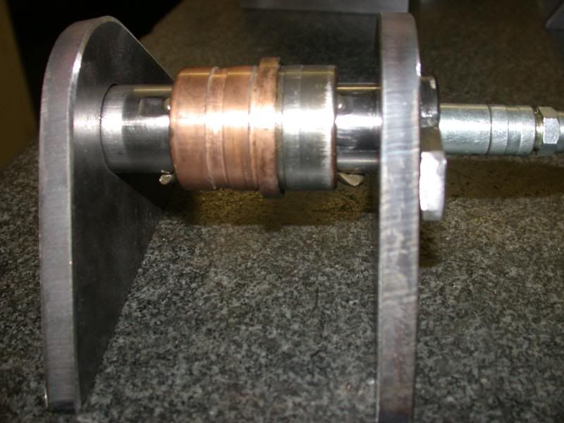
Post by bradblazer on Dec 7, 2009 1:33:33 GMT -5
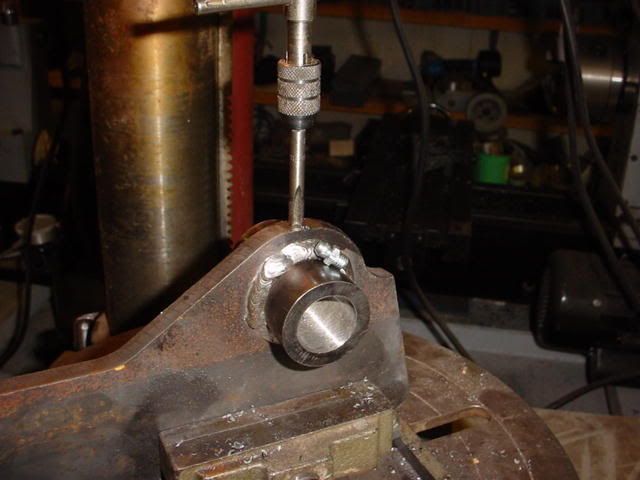
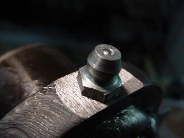
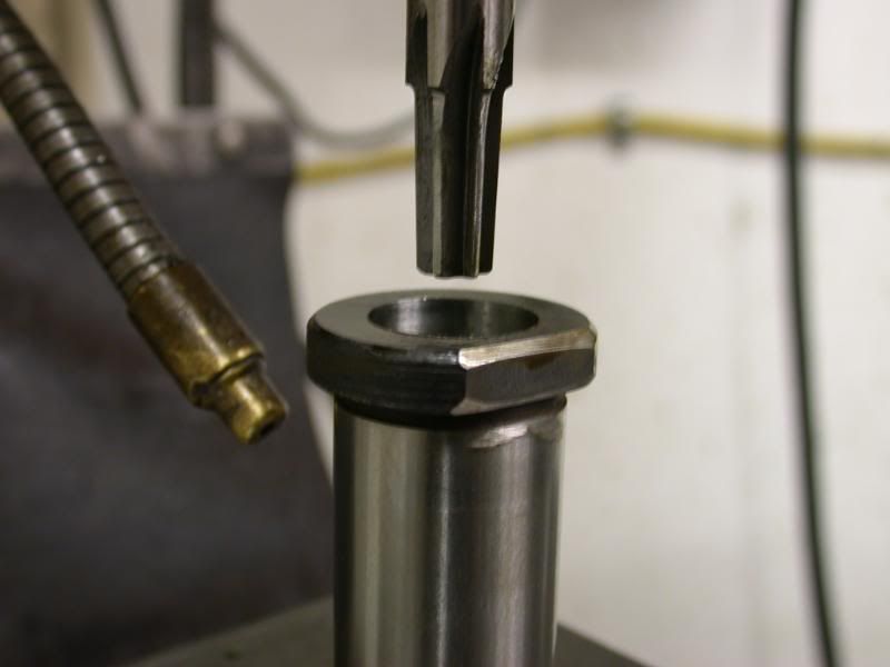
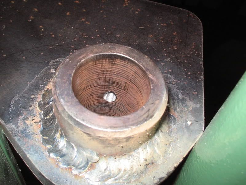
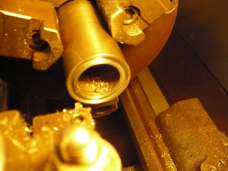
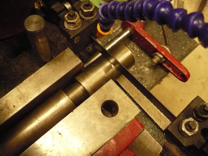
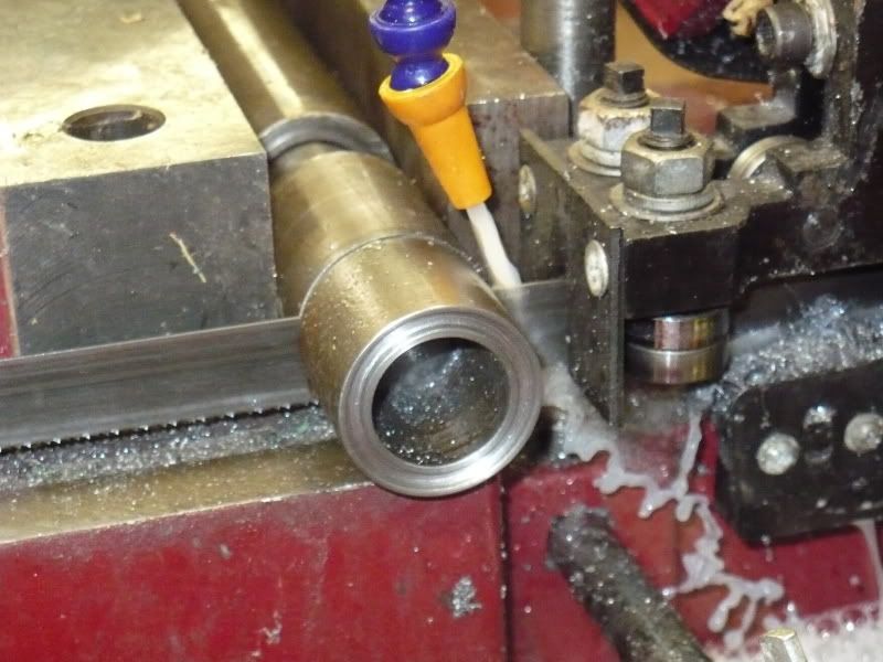
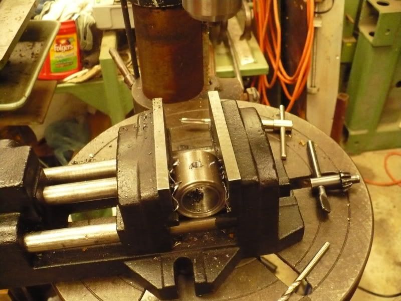
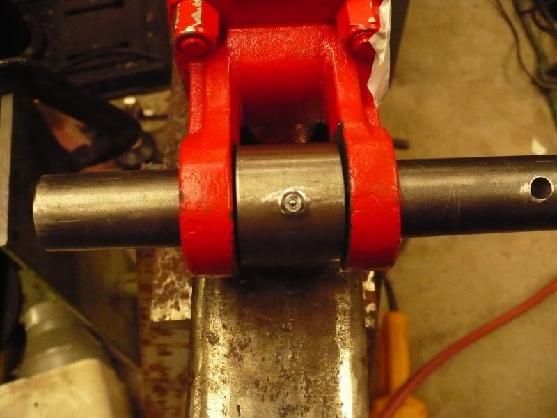
Finally I drilled and tapped the 1/4-28 hole for the zerk. Then I followed Rob's lead and did a test squirt. It looks pretty good. In practice if I want I can spin the bushing to grease the other side. 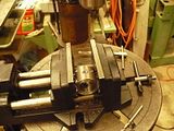  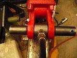 So that's it. I don't know if it was any less work than the way you guys did it. My reasoning is that the pins are supposed to be the wear part so I want them to be as simple as possible to replace. Brad |
|
PJ
CTW Expert
Posts: 176
|
Post by PJ on Dec 7, 2009 7:42:54 GMT -5
Finally I drilled and tapped the 1/4-28 hole for the zerk. Then I followed Rob's lead and did a test squirt. It looks pretty good. In practice if I want I can spin the bushing to grease the other side. So that's it. I don't know if it was any less work than the way you guys did it. My reasoning is that the pins are supposed to be the wear part so I want them to be as simple as possible to replace. Brad All I can say about your project is, you do damn nice work. Very professional. If it was needed, I would be proud to have you do work for me. PJ |
|
|
|
Post by bradblazer on Dec 7, 2009 21:06:49 GMT -5
Thanks PJ,
That's quite a compliment.
|
|
GuglioLS
Administrator
Jinma354 LE
Posts: 1,276
|
Post by GuglioLS on Dec 7, 2009 23:08:21 GMT -5
Interesting idea Brad, I like it allot.
What do you call this invention of yours? Amazing how much time and effort we all put into saving a 3 dollar pin and a $40 cylinder clevis. My prediction is these will last several generations. The lift arm pins on my 1953 Ford FEL are very similar to the ones Rob fabricated. When I was doing the skid steer upgrade. I pulled those 56 year old pins to find
a few spots looking like they were chrome polished, sort of like a cylinder rod and no ridges or out of round condition.
OK so where do I get a fancy adjustable goose neck gizmo like yours for band saw blade lubrication? I imagine something like that would work just as good with air for milling, turning and the like.
Larry
|
|