ronj
CTW Member

Posts: 72 
|
Post by ronj on Jul 12, 2009 2:40:02 GMT -5
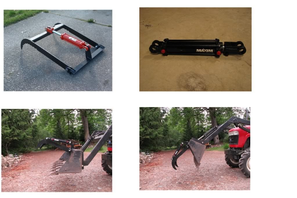
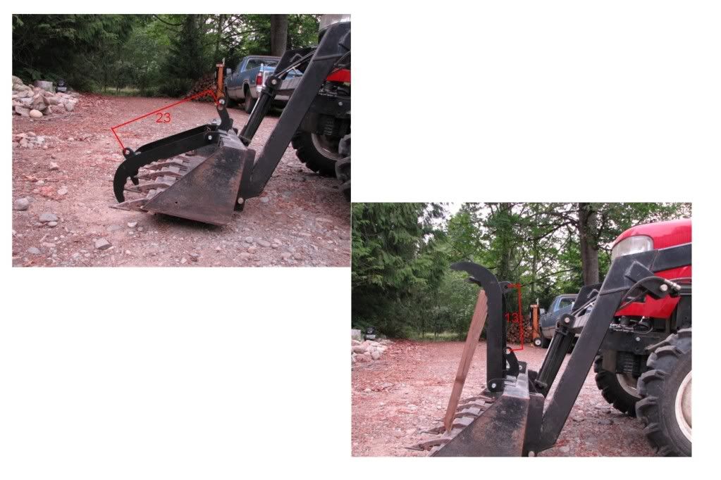
I am having a problem with mounting a grapple on the Coldwater FEL on my 284. The first picture is of the grapple assembly. The second picture shows the Maxim cylinder that came on my grapple assembly. It is model 218-298 with a retracted length of 16-1/4” and a stroke of 6”. The third and fourth pictures shows the grapple installed and in the retracted position. This means that the grapple would need to be removed whenever I wanted to really make use of the bucket for something other than grapple work. 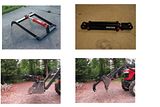 The fifth and sixth pictures show where I would like the grapple to be in the closed and open positions. This would mean that I need a cylinder that is 13” in a retracted mode with a 10” stroke. 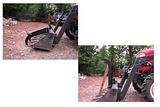 I talked to the hydraulic guy at Surplus Center and he said that cylinders with those dimensions are not made. I also have done a bunch of searching on the Internet and have not been able to find anything. Any of you got any ideas of what I can do? RonJ |
|
|
|
Post by Rich Waugh on Jul 12, 2009 3:26:53 GMT -5
Ron,
It looks like the current setup doesn't have the right geometry to allow that much movement. Seems to me that if you moved the attachment point of the cylinder back to the rear edge of the bucket you could get the movement you need. You'd have to move the other attachment point too, of course. You have a fixed amount of travel in that cylinder, so you need to make the geometry so that the ratios work out to give you the movement at the end of the arm.
This is something that I'm having a hell of a time putting into words, but I know it can be done. Whether or not you'll end up with the forces you need is something else, but that can be overcome by increasing the diameter of the cylinder or the pressure. It's all about leverage, right?
Try drawing out the side view of the bucket and the grapple arm on some paper and fiddle around with the attachment points and swing arcs from them to see where ou need to be to get what you need.
Or, just wait until Rob sees your question and figures it out for you. He does that shit better than anyone else, form what I can see. :-)
Rich
|
|
|
|
Post by Ranch Hand on Jul 12, 2009 7:05:05 GMT -5
Hi ronj,
The grabble is to big/large for the bucket ...... sorry. Meaning the arms / claws are to long for that bucket.
Ronald
Ranch Hand Supply
|
|
GuglioLS
Administrator  Jinma354 LE
Posts: 1,276
|
Post by GuglioLS on Jul 12, 2009 9:12:23 GMT -5
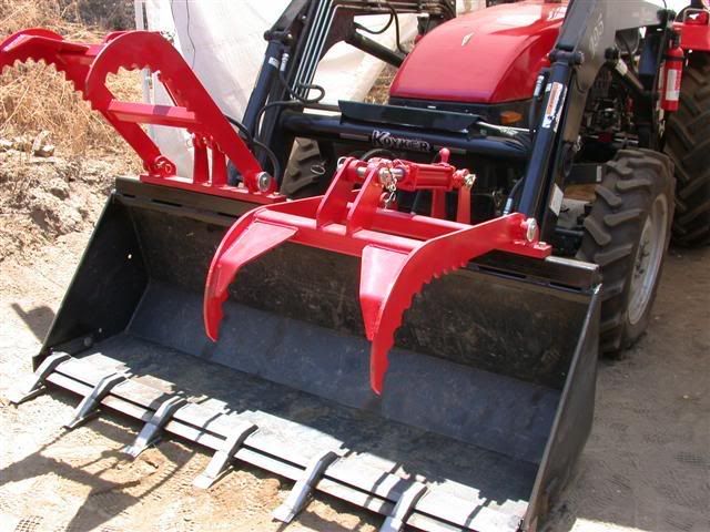
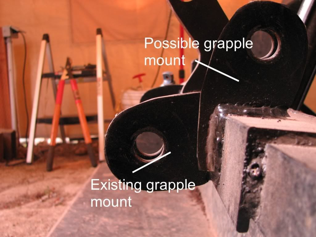
Ron, The pivot point for the jaws needs to be placed on top and probably rear of center on that top flat of the bucket. The cylinder pivot point will need to be behind the bucket and behind the jaw pivot points. Like Rich said the cylinder attachment point on the jaw end will have to move back (toward the tractor) as well. The geometry can be corrected if your willing to cut off all the brackets and make new ones. The jaws can be salvaged. Rob or I can draw this up in autocad and make it work if you give dimensions of your bucket and jaws. Check this thread in detail CLICK HERELarry |
|
3RRL
Administrator
Huge Kama
Posts: 2,027
|
Post by 3RRL on Jul 12, 2009 12:35:49 GMT -5
Hi Ron,
Just saw your thread.
Personally, I like that the grapple is that long and reaches out to/in front of your tooth bar.
It becomes truly very effective in that position for grabbing stuff. Second, the guys are right that the geometry or location of the cylinder pivot points and the grapple jaw pivot needs to re-arranged for it to open and close like you want. Third, I don't think you need the jaws to open quite as much as in your photo.
Mine don't open that much and they work just fine. (on my Kama) I have NEVER had my grapples off since installing them over 3 years ago. Plus, you don't want them so "open" that if you hit/push something with them while open that much that the jaws will flip backwards past the pivots. That could and will happen unless there is a positive stop to prevent it. In regular use, I often drive into a pile of brush or logs which places pressure pushing those jaws back and you need to be aware of that. Loretta's grapples (and Larry's and Ken's and many others on TBN) open quite good and close good. I designed all of them plus a stop in them to keep from pushing over.
Last is the way to do it.
You find the right cylinder stroke ... one that is in stock (standard one and inexpensive) and needs no alterations to work. I would use the one you have (obviously since it's the least expensive). Then you locate the cylinder pivot points using that stroke. You may need to move the cylinder pivot points higher or lower, front or back to achieve what you desire. There is a relationship between the Jaw pivot and the cylinder pivot that will give you the best combination. That might mean making new brackets or at least moving them.
Are you up for that?
Rob-
|
|
ronj
CTW Member
Posts: 72
|
Post by ronj on Jul 13, 2009 3:02:58 GMT -5
Rich and Ronald,
Thank you for your input. I appreciate it.
Larry,
Thank you for including that URL of the Grapple work that you did. I did a search on this site and thought that I looked at everything, but I missed that. Guess that I don’t understand the proper way to use the search capability.
Rob,
Thanks for your comments.
I am up for it with a couple of concerns:
1. I need to see (visualize) what the end result will look like to completely commit and.
2. My lack of skills and equipment for doing this. I don’t have all of the stuff that you and Larry have.
I downloaded many of the pictures from Larry’s thread and I want to study them.
RonJ
|
|
|
|
Post by Rich Waugh on Jul 13, 2009 12:27:44 GMT -5
Ron,
If you have a 4-1/2" angle grinder, a 1/2" electric drill, a welder of any sort and a tape measure you've got about all you really need in the way of shop tools to do this job. The other things you'll need are a piece of cardboard, a pencil, an engineer's or architect's scale (or calculator),scissors and a piece of string (optional).
I would definitely start by making a scale drawing of your bucket end including the teeth on a piece of cardboard. Then do likewise for the grapple arm, being sure to include the pivot point. Make a scale drawing of the hydraulic cylinder showing it with the rod both extended and retracted. You can also make a scale drawing of the mounting bracket for the hydraulic cylinder, too. Then take the scissors and cut out the grapple arm, the hydraulic cylinder (extended length) and mounting bracket so you can place them on the drawing of the bucket and move them around until the geometry works right. Once you get things placed so that you get it the way it needs to be both open and closed, you can take measurements off the drawing and scale them back up and get busy cutting and welding.
This is actually the way that Larry and Rob (and I) do it, we just use a CAD drawing program to do the drawing and moving instead of using little pieces of paper or cardboard. Rob and Larry do it in CAD because they're really good with that stuff and thenthey can take the file to the plasma cutter guy and have him cut steel directly from the file. I do it in CAD because I'm a really "green" kind of tree-hugging, Earthshoe-wearing, granola-eating old ex-hippie who only wants to do what is right for Mother Earth and save the trees that you'll be sacrificing to make your little paper dolls. (GRIN)
Okay, if truth be told, I usually do this stuff with a piece of chalk on the floor of the shop and than hack away with the torch and welder until things accidentally work right. But don't spread that shit around, will ya? I got a rep to protect! :-)
In case you're wondering about the piece of string, that's what I use on the shop floor to draw the arcs of travel of the grapple arms. You shouldn't really need it unless you actually like working on your hands and knees on a concrete floor instead on a nice clean desktop. I don't have a clean desktop, so....
I hope this helps - I know you can do it!
Rich
|
|
ronj
CTW Member
Posts: 72
|
Post by ronj on Jul 14, 2009 3:50:41 GMT -5
Larry, Rob and Rich, Is this kind of what you were describing? 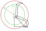 It may not look like much, but this was an all day task. I have a drawing program called DeltaCad which is not a true CAD program. Movements, rotations, etc are all pretty much manual - but drawing is to scale. It is too difficult to try What-Ifs, so I just picked a couple of mounting points. Does this look like the best way to do it - or do you have other thoughts? Thank you for your interest and help! RonJ |
|
|
|
Post by Rich Waugh on Jul 14, 2009 17:25:31 GMT -5
That looks okay to me, though I don't really think you need all that much "openness" on the thing. The vector your cylinder will be operating at coming off of full open may not give my much available squashing force until it gets about a third of the way closed, bu tthat shouldn't cause any problems.
If you want to see how it will function, cut out the pieces and try pinning the arm at the pivot point with a thumbtack and then pushing on the arm in the same direction the cylinder would. You'll see what I'm talkng about regarding the force vectors. Rob or Larry can explain this stuff more clearly than I can - I know what's going on but have a tough time explaining it.
Looks like you're on the right track, anyway. Was that easier than cutting out pieces of cardboard?
Rich
|
|
GuglioLS
Administrator
Jinma354 LE
Posts: 1,276
|
Post by GuglioLS on Jul 14, 2009 22:46:34 GMT -5
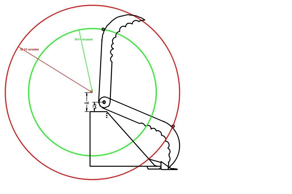
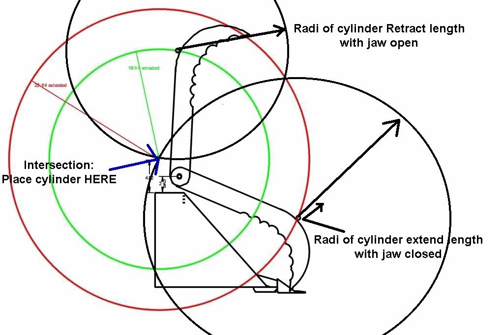
RonJ, Looks great what format does your drawing software use? What I mean is what extension can you save the file in? such as .dwg, .dxf, dwt, etc. If you e-mail me the file,I might be able to read it by import into my autocad and offer exact locations for the pivot points. Don't worry about loss of forces when the jaws are fully open. @ 2300 psi a 2" cylinder has 7222 pounds of push force. even at 8:1 loss that's still 900 pounds of clamping force. 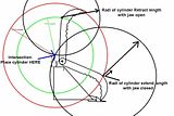 To get the exact location using a 6" stroke cylinder draw a 22.25" radii circle around the jaw cylinder mounting point, next draw a 16.25" radii circle around the jaw cylinder mount with the jaw open, where the two circles intersect that is where the cylinder is mounted. Keep in mind a few 16 Th's here or there will have a dramatic effect of how far the jaws open or close, accuracy counts. BUT your have some "play" by rotating the clevis on its threads that screws in / out on the rod end to compensate for length. Larry |
|
GuglioLS
Administrator
Jinma354 LE
Posts: 1,276
|
Post by GuglioLS on Jul 14, 2009 23:04:13 GMT -5
"Rob or Larry can explain this stuff more clearly than I can - I know what's going on but have a tough time explaining it."
To the best of my ability and understanding (results may vary)
Ratio of loss or gain, is expressed as cylinder stroke over distance of arc movement. In other words if the cylinder stroke is 6" and the jaw arc movement is 24" (at the cylinder attachment point) then force is 6/24ths (1/4) of the available cylinder force. Brad would know for sure as he's our resident expert at quantum mechanics. :-)
Also of particular note: as the jaws close they will exponentially accelerate as they get closer to the closed position. Don't be surprised when you see that happen, it's quite normal for this type of setup.
Larry
|
|
|
|
Post by bradblazer on Jul 15, 2009 0:10:55 GMT -5
The easiest way to figure force at the tips is to think of it as a lever. Imagine a line through the middle of the cylinder and another line through the pivot axis of the grapple. The distance between those lines at their closest point divided by the length of the grapple (pivot to tip) is the fraction of cylinder force available at the tip.
The inverse of that fraction is the speed ratio. Of course the fraction changes continuously as the grapple operates, explaining the acceleration noted by Larry.
Hopefully you can just modify the base end mount with your new cylinder.
|
|
GuglioLS
Administrator
Jinma354 LE
Posts: 1,276
|
Post by GuglioLS on Jul 15, 2009 0:36:31 GMT -5
RonJ,
OAN - I have virtual free access to a CNC plasma cutter. (I'm the primary operator now - go figure) If you don't mind and I can get your exact scale model drawing into my autocad to design a cylinder to bucket mounting bracket I would gladly do so and cut it out for you. It could be my small way of "paying it forward" for all the favors Rob, Ken, Ed, Brad, Scott and many others have done for me. What say you?
Larry
|
|
ronj
CTW Member
Posts: 72
|
Post by ronj on Jul 15, 2009 2:24:35 GMT -5
Was that easier than cutting out pieces of cardboard? Rich Not really, but you told me to save the trees by not using paper dolls (GRIN back) Larry, Thank you for the offer. My software will save files as .dc;.dwg;.dfx;dxb Also thank you for that modified picture. It has helped to clarify things in my mind. After looking at the pictures and possible mount points, I want to study things some more. I am thinking that perhaps by reversing the mounting bracket on the FEL, I may be able to make use of it. But I need to draw it up to scale to see if it fits as close to what is needed as it looks. RonJ  |
|
ronj
CTW Member
Posts: 72
|
Post by ronj on Jul 15, 2009 2:54:33 GMT -5
RonJ, OAN - I have virtual free access to a CNC plasma cutter. (I'm the primary operator now - go figure) If you don't mind and I can get your exact scale model drawing into my autocad to design a cylinder to bucket mounting bracket I would gladly do so and cut it out for you. It could be my small way of "paying it forward" for all the favors Rob, Ken, Ed, Brad, Scott and many others have done for me. What say you? Larry Larry, That is a fantastic offer-Thank You! Hope that you don't mind, but I shared your note with some others. We seem to think that things are so bad and getting worse and lose sight of the fact that there are still generous people out there who want to help. I thank you also for reminding us of that. RonJ |
|